Stacking of Gloves

a glove and glove technology, applied in the field of glove stacking apparatus, can solve the problems of difficult ejecting of the stack, the stack does not move downwards, and the size of the boxed glove is an issue, so as to simplify and speed up the operation of the glove placement. , the friction between the side surfaces and the glove stack is reduced

Inactive Publication Date: 2015-08-20
SAFEDON
View PDF17 Cites 17 Cited by
  • Summary
  • Abstract
  • Description
  • Claims
  • Application Information

AI Technical Summary

Benefits of technology

[0020]Because the overall shape of the stack in terms of width and depth is determined by the orientation of the gloves deposited at the opening and by contact with the opening, the angled surface provides greater space between the stack of gloves and the receptacle inner surface. This reduces friction between the receptacle inner surfaces and the stack of gloves as the floor moves away from the opening as the stack is built up. At the same time, the contact between the stack of gloves and one or more surfaces around the receptacle opening stabilises the orientation of the stack of gloves, and prevents this from sagging or moving to one side, even if the angle and extent of the inner surface is sufficiently large for there to be no contact between the stack of gloves and the receptacle inner surfaces between the angled surface and the descending floor.
[0054]If the friction between the side surfaces and glove stack is reduced according to the invention, then it has been found that the movable flaps can provide sufficient downward force to keep the top of the stack approximately level with the receptacle opening as the floor moves away from the opening. The apparatus and method according to the invention therefore does not need any interaction between the glove placement means and the top of the stack in order to keep the stack moving into the receptacle. This greatly simplifies and speeds up the operation of the glove placement means, which then does not need to make any contact with the top of the stack of gloves.

Problems solved by technology

The size of boxed gloves is an issue owing to the need to minimise the space needed to store gloves, or the size of dispensing apparatus holding boxed gloves.
The type of packing receptacle works well as the stack is growing, but a problem can arise when the stack is to be ejected upwards from the receptacle for insertion into a container, which may be either a glove dispenser or the plastic bag or card material to form a packet for subsequent loading into a glove dispenser.
As a result, after the stack has reached its full height and when the base starts to move upwards, it is possible that the portions of the gloves in the periphery of the stack nearest the floor will drag against the inner surfaces of the receptacle containing the stack and fall into and get trapped in the gap between the edge of the floor and an inner surface of the packing receptacle.
The inventors have noticed a problem when using the known types of packing receptacle to form taller stacks consisting of up to 500 of such gloves.
In this case, the friction between the stack and the inner surfaces of the receptacle becomes so great that the stack does not move downwards evenly as the floor is lowered, and it also becomes difficult to eject the stack.
It is possible to reduce the friction by increasing the internal horizontal dimensions of the receptacle, but this also reduces the ability of the receptacle inner surfaces to contain and define the outer boundaries of the stack of gloves.
The result of this is that the stack is wider such that this will no longer fit inside a dispensing box having dimensions of about 130 mm wide by 120 mm deep.

Method used


Image

  • Stacking of Gloves
  • Stacking of Gloves
  • Stacking of Gloves

Examples


first embodiment

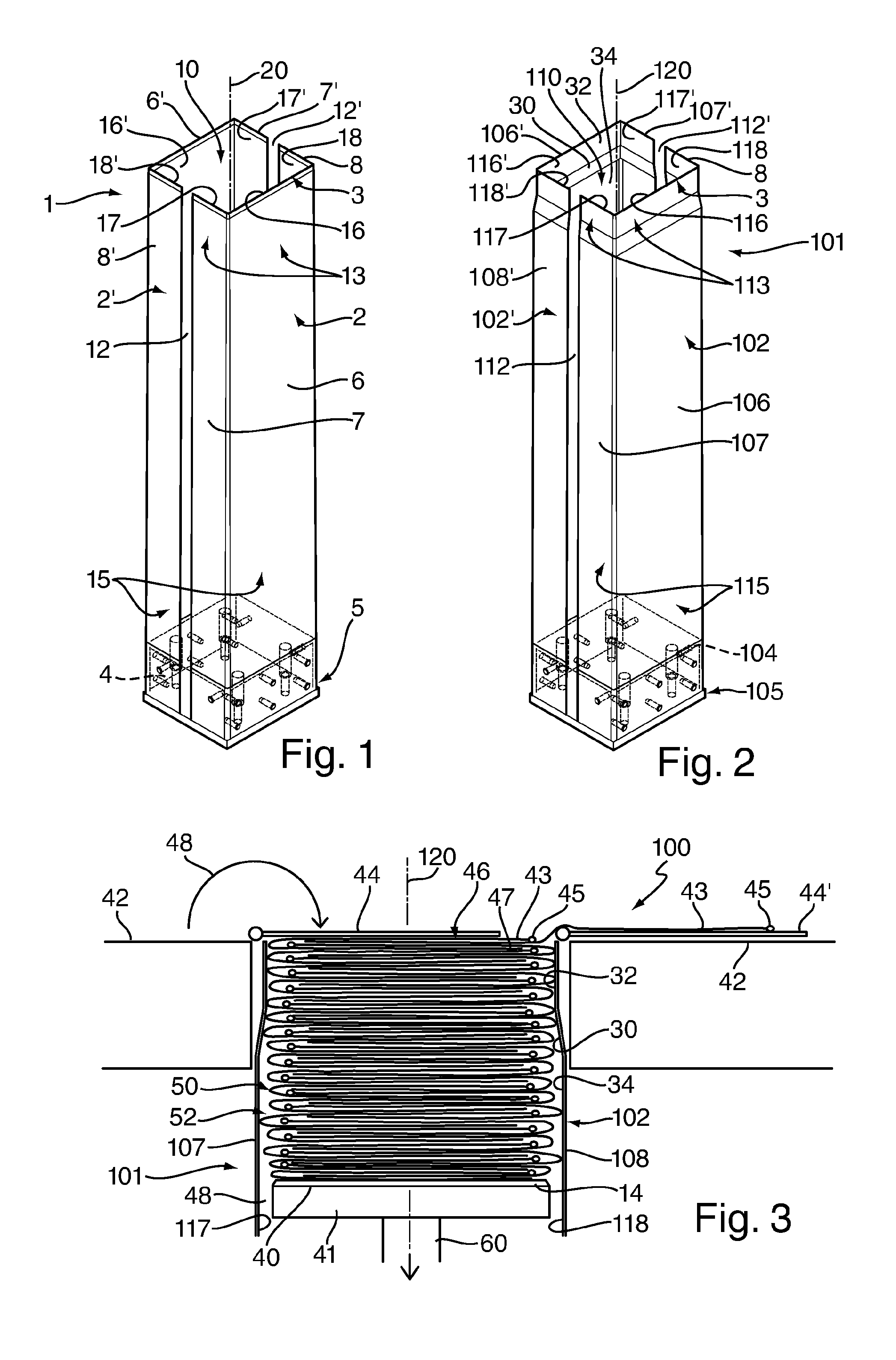
[0063]FIG. 1 is perspective view of a receptacle 1 for use in a glove stacking apparatus. The receptacle 1 is formed from a pair of similar sleeve halves, 2, 2′, bolted together at a base 4. The sleeve halves each have one continuous side wall 6, 6′ which is central between a pair of similar partial side walls 7, 8, 7′, 8′. At a first end 3 of the sleeve halves is an opening 10, which in this example is substantially rectangular or nearly square. At an opposite end 5 of the sleeve is the base 4. The arrangement is such that the continuous side walls 6, 6′ are on one pair of opposite sides of the rectangular opening 10 defined by the receptacle, and the partial side walls 7, 8, 7′, 8′ are on another pair of opposite sides of the rectangular opening.

[0064]Each side wall has a first portion (generally indicated by reference numeral 13) proximate the first end 3 and a second portion (generally indicated by reference numeral 15) farther away from the first portion 13.

[0065]The partial si...

second embodiment

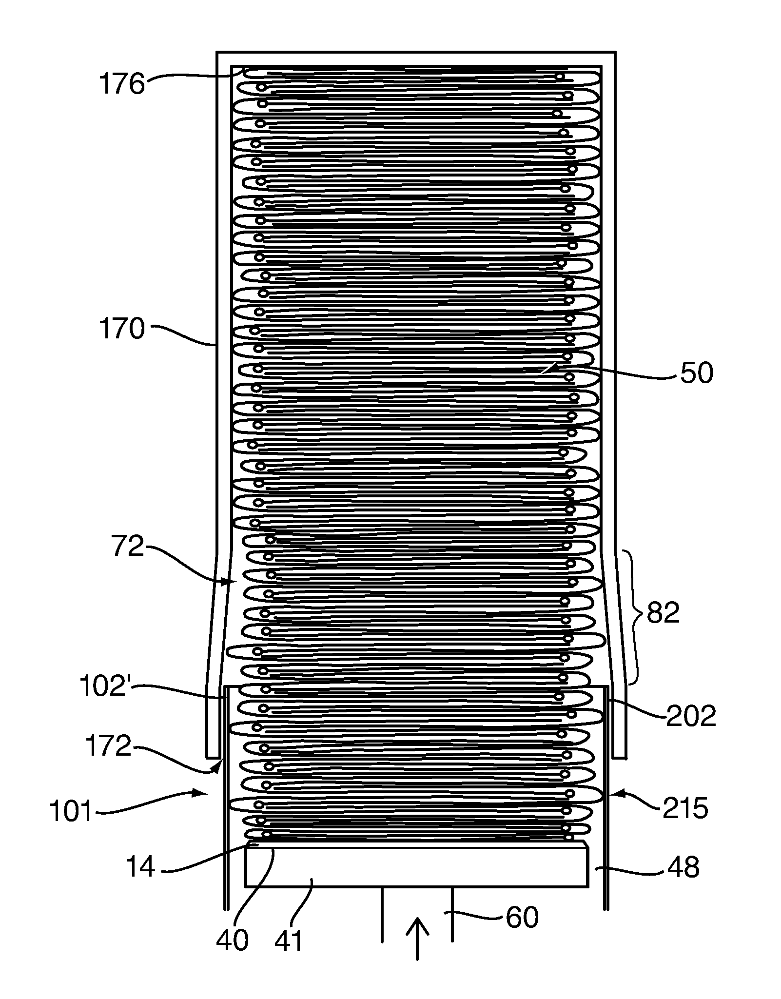
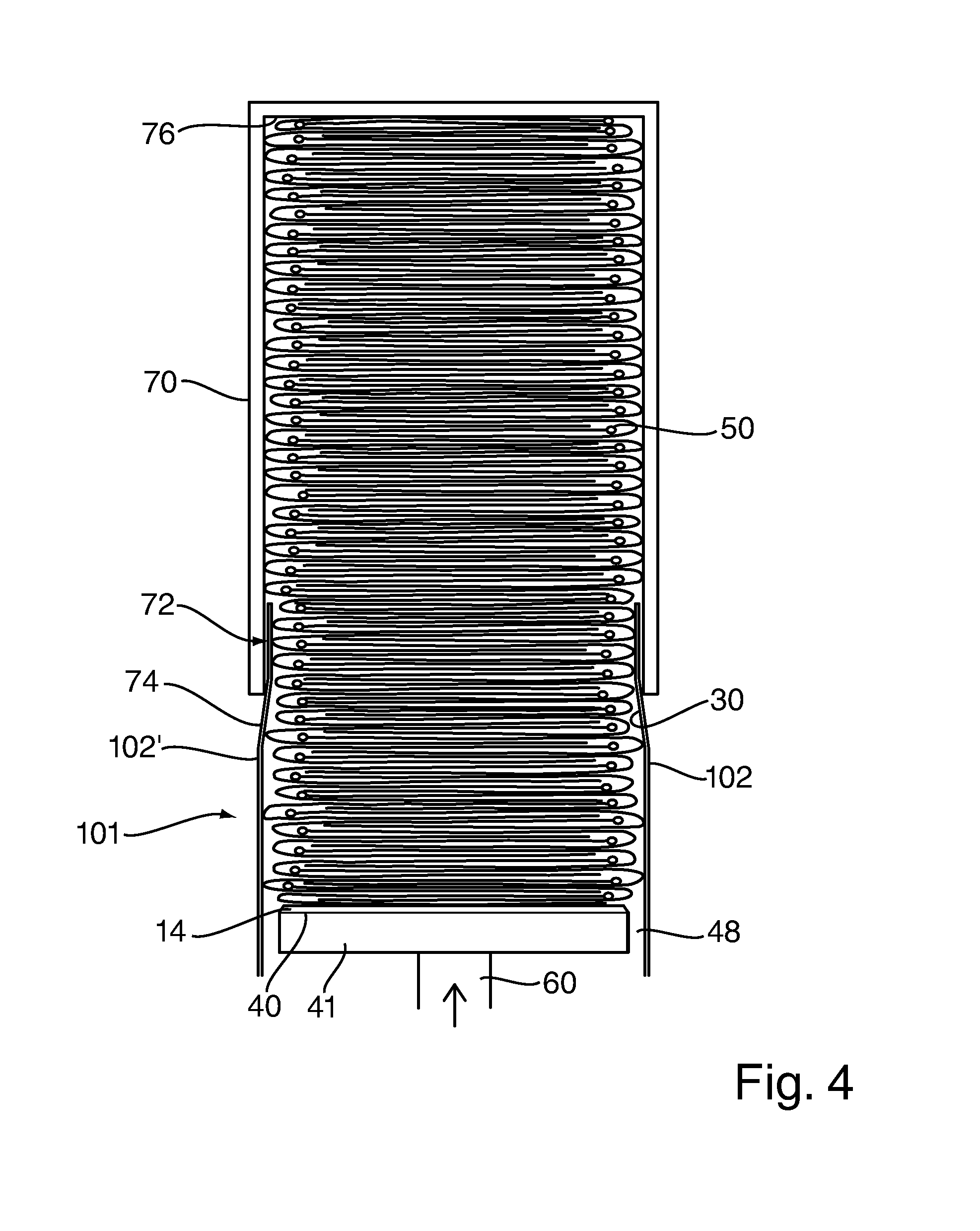
[0080]Once the gloves are stacked in the receptacle 1, 101, the stacked gloves may be removed from the receptacle into a container 70, as illustrated in FIG. 4 in respect of the The gloves are removed from the receptacle by placing an open mouth 72 of the container 70 over the receptacle and moving the base 41 upwards to press the stacked gloves 50 into the open container. The container is shown only schematically in outline, and may consist of a single box-like component, referred to as a packing box, for example made from a rigid plastics material, into which the stacked gloves are temporarily packed, prior to transfer into a glove dispensing box. Alternatively, the container 70 may be a glove dispensing box having a dispensing aperture and made, for example, from a card material, in which case flaps of the box may be closed and sealed after filling of the box with gloves, or the container 70 may be an open plastic bag made from plastic film material which has a closable opening ...


PUM


Abstract

The present invention relates to a glove stacking apparatus that has a receptacle into which gloves are placed for preparing a stack of gloves prior to packing into a container such as a glove dispensing box, and to a method of stacking gloves prior to packing into a container.

Description

BACKGROUND[0001]a. Field of the Invention[0002]The present invention relates to a glove stacking apparatus that has a receptacle into which gloves are placed for preparing a stack of gloves prior to packing into a container, for example a glove dispenser, and to a method of stacking gloves using such a glove stacking apparatus for preparing a stack of gloves prior to packing into a container.[0003]b. Related Art[0004]Disposable hygienic gloves, in particular ambidextrous medical examination gloves, are used in vast numbers in hospitals, clinics, and doctors' surgeries. Such gloves are often ambidextrous and are supplied not in individual sterile packages, but packed inside a glove dispenser, for example an inexpensive card material dispensing box that has one or more dispensing apertures through which gloves can be pulled out one at a time by a user. To help control infection and the rise of infectious bacteria resistant to multiple antibiotics, it is important that the user does no...

Claims


Application Information

Patent Timeline
Patent Type & Authority Applications(United States)
IPC IPC(8): B65B35/50B65G57/03B65B63/02B65B5/06B65B25/20
CPCB65B25/20B65B5/06B65B5/108B65G57/035A61B42/40B65B35/50B65B5/10B65B63/02B65G57/03
Inventor STOLLERY, JONATHAN WILLIAMSTOLLERY, KIM MARIE
Owner SAFEDON
Why Eureka
Try Eureka