Touch sensors and touch sensing methods

Active Publication Date: 2015-08-20
TOUCHNETIX
View PDF5 Cites 10 Cited by
  • Summary
  • Abstract
  • Description
  • Claims
  • Application Information

AI Technical Summary

Benefits of technology

The patent relates to a method of designing a sensor that minimizes the distance between neighboring electrodes. The technical effect of the invention is to improve the accuracy and precision of the sensor.

Problems solved by technology

The inventors have recognised that in some cases a conventional electrode layout coupled to a conventional controller may not be appropriate.
In particular, in some situations it may be inconvenient or impossible to establish connections from a touch sensor controller chip (IC) to more than one side / edge of a sensing surface.
For example, this may be due to a limited availability of space adjacent the sensing area in which to route connections to other edges of the sensing surface.

Method used


Image

  • Touch sensors and touch sensing methods
  • Touch sensors and touch sensing methods
  • Touch sensors and touch sensing methods

Examples


Embodiment Construction

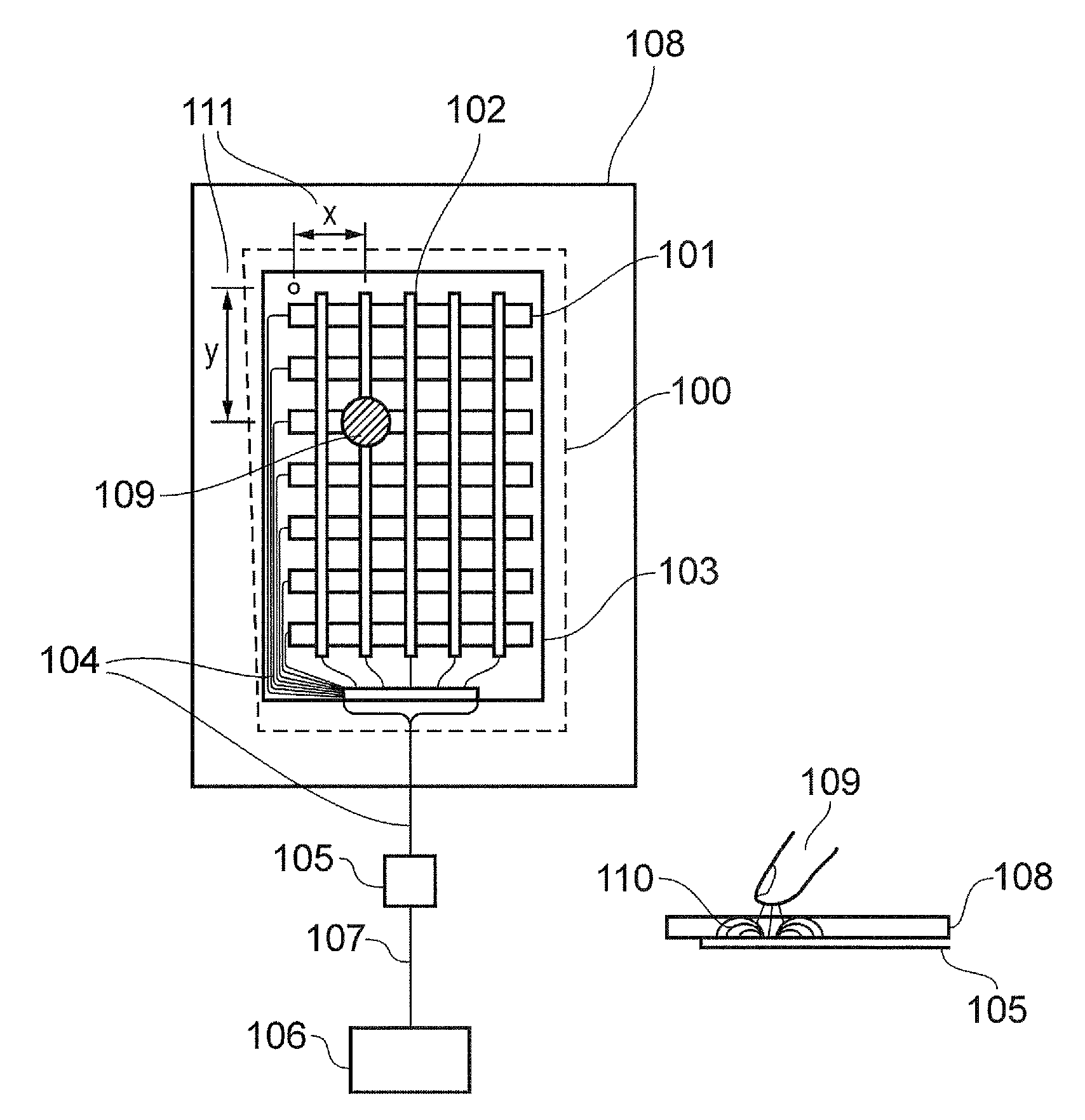
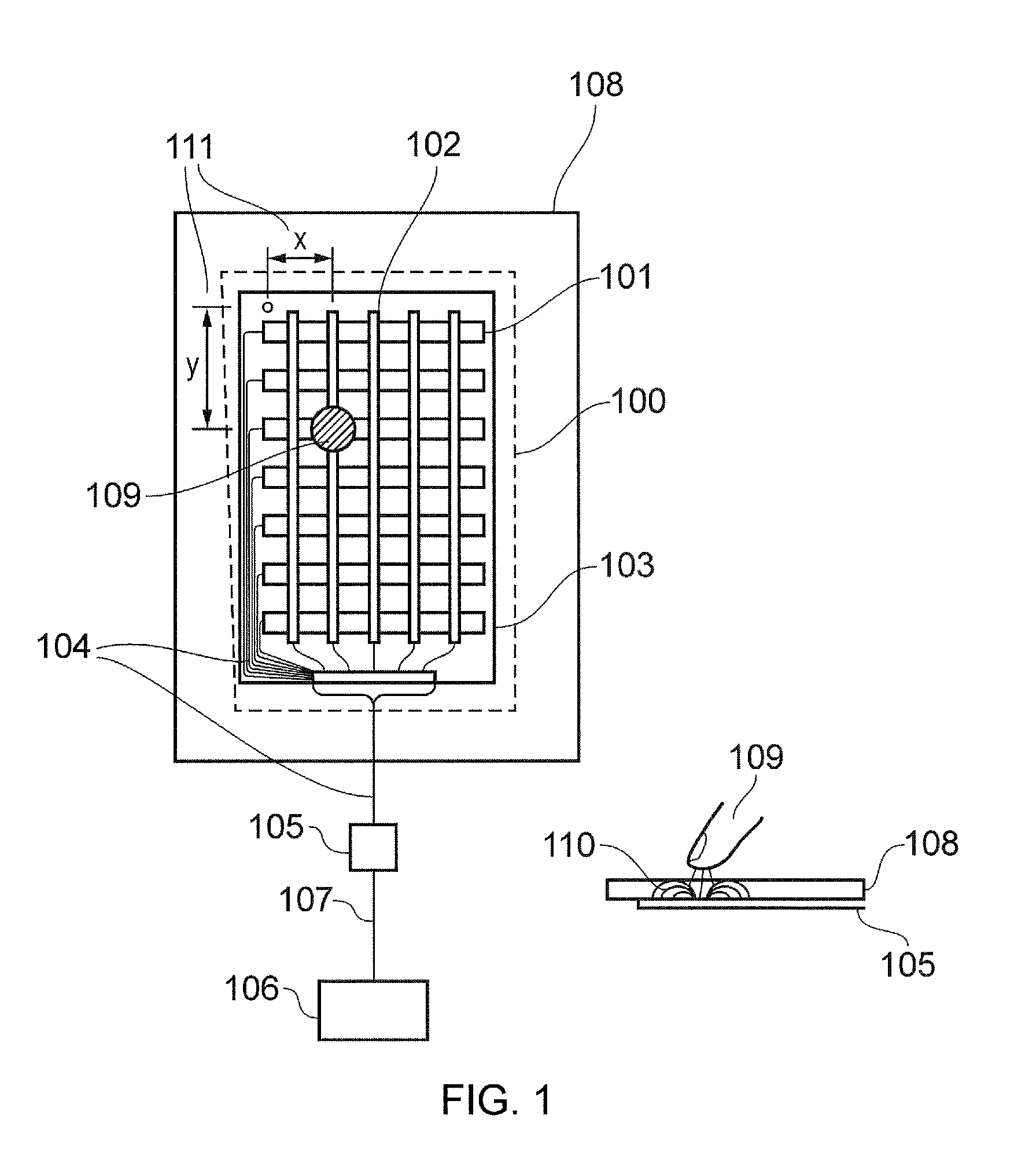
[0047]In touch-sensor applications there is often a desire to provide a sensing surface that which is as large as possible within a defined space. For example, there is often a desire for a large touch-sensitive surface to be provided within a relatively compact device, such as a handheld computer / tablet or mobile phone, for example. However, with established techniques there is generally a requirement for a “dead” region surrounding a touch sensitive surface that is needed for routing electrical connections to the various electrodes comprising the sensing surface. For example, for the conventional sensor schematically represented in FIG. 3 there is a need for traces to run down the left-hand side of the sensing surface to connect to the horizontally-aligned electrodes. This restricts the extent to which the sensor can extend across the full width of a device in which it is incorporated. Because of this there can be a desire to simplify the manner in which electrical connections can...


PUM


Abstract

A touch-sensitive position sensor is disclosed. The sensor comprises an array of first electrodes and an array of second electrodes arranged in a pattern to provide a sensing surface, wherein at least some of the first electrodes and the second electrodes are arranged to follow paths which are non-linear within the sensing surface such that there are ends of the first electrodes and ends of the second electrodes which meet a common edge of the sensing surface. A controller is coupled to respective ones of the first electrodes and the second electrodes and arranged to determine a reported position for an object adjacent the sensing surface by measuring changes in an electrical parameter e.g. capacitance or resistance, associated with the first electrodes and the second electrodes which is caused by the presence of the object. The controller is further operable to provide an indication of the reported position in a first coordinate system defined relative to the first electrodes and the second electrodes, the sensor further comprises a processor arranged to receive the indication of reported position from the controller in the first coordinate system and to transform the reported position to an output position in a second coordinate system, wherein the transform is based on the non-linear pattern of electrodes. Thus, a sensor having electrodes which are distorted so as to meet a common edge may be provided for ease of connectability, with the distortion been accounted for through the transform performed by the processor.

Description

BACKGROUND OF THE INVENTION[0001]The present invention relates to the field of touch sensors, including touch screens and touch pads, and their associated control chip(s). In particular, embodiments of the invention relate to designs for electrode patterns for such sensors for aiding connectability.[0002]A capacitive touch sensor can be generalised as one that uses a physical sensor element comprising an arrangement of electrically conductive electrodes extending over a touch sensitive area (sensing area) and a controller chip connected to the electrodes and operable to measure changes in the electrical capacitance of each of the electrodes or the mutual-capacitance between combinations of the electrodes.[0003]FIG. 1 schematically shows principal components of a generic conventional capacitive touchscreen comprising a physical sensor element 100. The touch screen is represented in plan view (to the left in the figure) and also in cross-sectional view (to the right in the figure).[00...

Claims


Application Information

Patent Timeline
IPC IPC(8): G06F3/041G06F3/044
CPCG06F3/0416G06F2203/04111G06F3/044G06F3/0446G06F3/045G06F3/047
Inventor ROBERTS, STEPHEN WILLIAMSLEEMAN, PETER TIMOTHYARD, CHRISTOPHER KYLE
Owner TOUCHNETIX
Why Eureka
Try Eureka