Electric power conversion apparatus

a technology of electric power conversion and electric motor, which is applied in the direction of power conversion systems, electrical devices, dc-ac conversion without reversal, etc., can solve the problems of increased cost, increased weight, and large capacity of filters, and achieves low cost and small size

Active Publication Date: 2015-08-20
KK TOSHIBA
View PDF8 Cites 26 Cited by
  • Summary
  • Abstract
  • Description
  • Claims
  • Application Information

AI Technical Summary

Benefits of technology

[0012]Accordingly, an object of an embodiment is to provide a small-sized electric power conversion apparatus capable of outputting a voltage / current waveform with a low level of harmonics without a harmonic suppression filter while eliminating a high-cost, and large-sized reactor such as a buffer reactor, and further making an initial charging rush current suppression resistor low in cost, and small in size.Solution to Problem

Problems solved by technology

However, in order to reduce the harmonic components flowing into the power system to a level at which other devices are not adversely affected, the capacity of the filter becomes large, and an increase in cost, and an increase in weight are brought about.
In this circuit form, in order to control the voltage value of the DC capacitor serving as a constituent element of each converter unit to be constant, it is necessary in principle to make a reflux current in the DC power supply flow at all times. The three phases of power are connected to one DC power supply, and hence when DC voltage resultant values of the respective phases differ from each other even to a small extent, there is a danger that an excessive short-circuit current flows between the phases to thereby destroy the apparatus.
The buffer rectors bring about an increase in size and an increase in cost of the apparatus.

Method used


Image

  • Electric power conversion apparatus
  • Electric power conversion apparatus
  • Electric power conversion apparatus

Examples


first embodiment

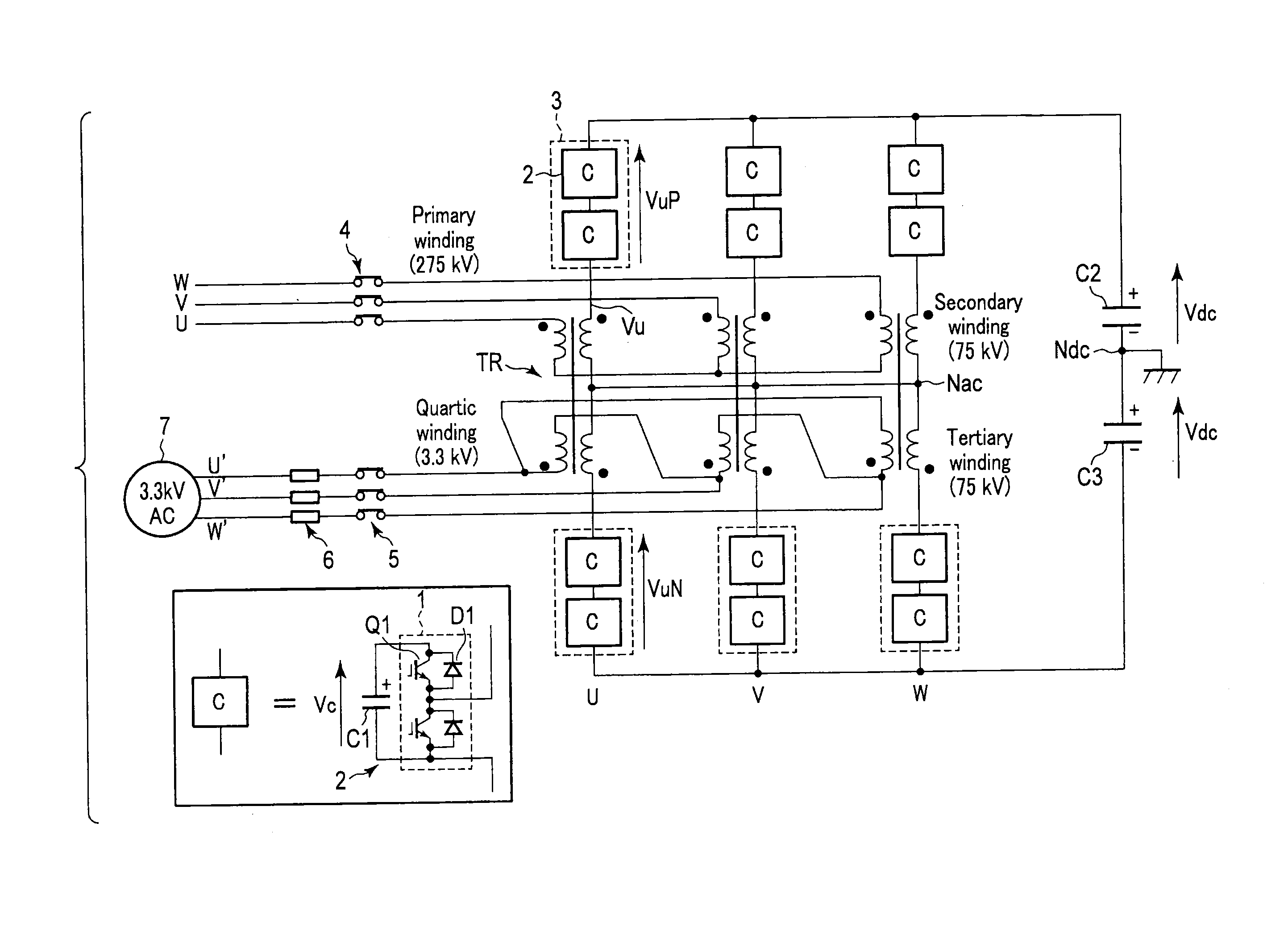
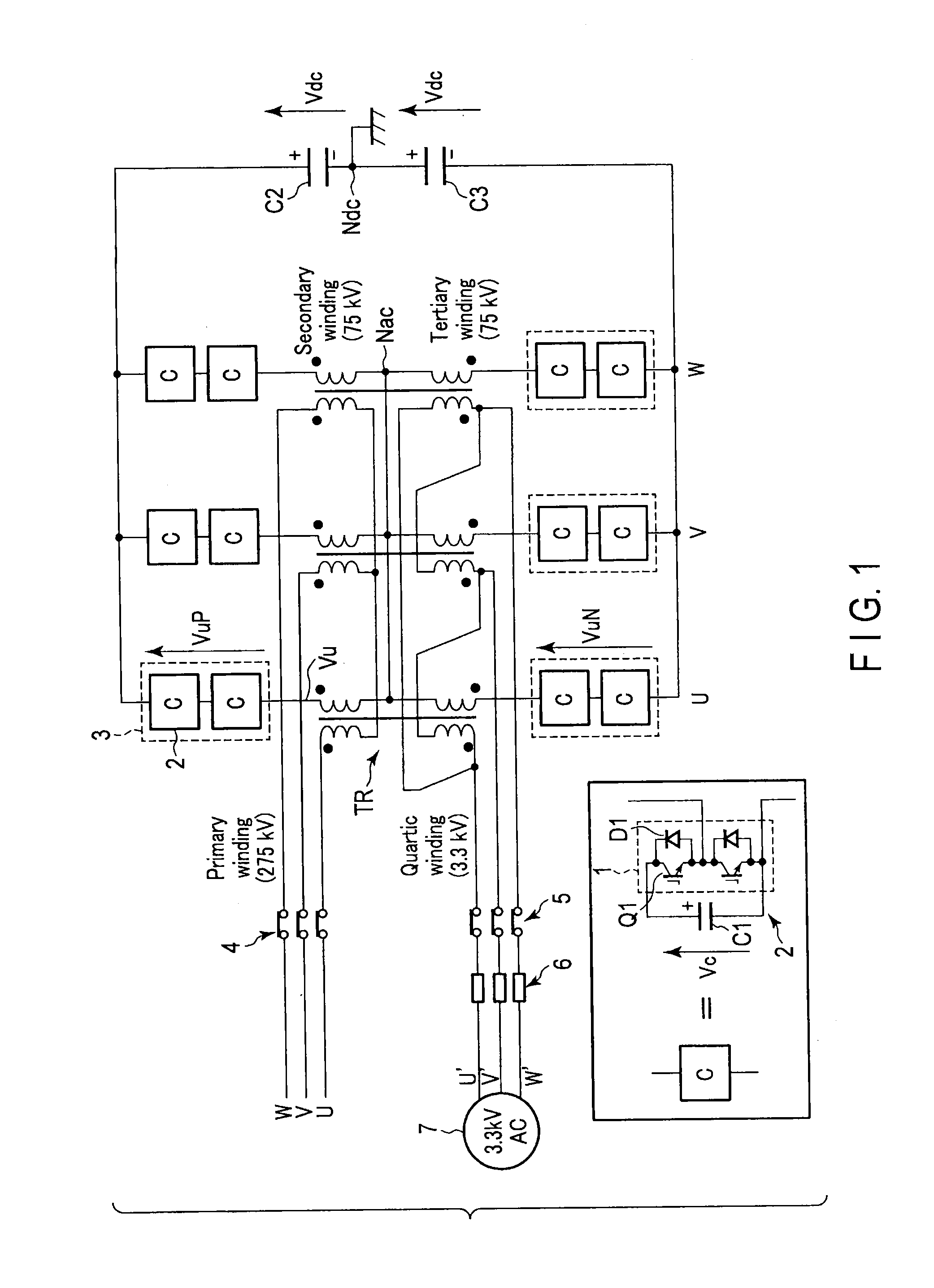
[0022]FIG. 1 is a view showing the configuration of an electric power conversion apparatus according to a Hereinafter, this electric power conversion apparatus (converter) will be described as an electric power conversion apparatus (converter) configured to power-convert three-phase 50 Hz power supply into DC power through an isolating transformer. However, this electric power conversion apparatus can operate also as an electric power inverter configured to convert DC power into three-phase 50 Hz AC power by control of reversing the polarity of a current command value or the like.

[0023]A phase arm 3 is constituted by connecting N (N=2 in this example) converter units in series, the converter unit being constituted of a chopper bridge unit converter 2 formed by connecting a leg 1 in which two switching elements Q1 provided with self-arc-extinguishing capability are connected in series, and a capacitor C1 in parallel with each other.

[0024]One end of a phase arm on the positive side i...

third embodiment

[0054]FIG. 5 is a view showing the configuration of an electric power conversion apparatus according to a

[0055]In this electric power conversion apparatus, in contrast to the initial charging circuit 9 of the electric power conversion apparatus of FIG. 4, a three-phase short-circuiting switch 10 is provided between a circuit breaker 5, and initial-charging / discharging resistors 6, the circuit breaker 5 is provided on the three-phase AC power supply 7 side, and the initial-charging / discharging resistors 6 are provided on the tertiary winding side of the transformer.

[0056]After the primary winding circuit breaker 4 is opened to stop the operation of the electric power conversion apparatus, a capacitor C1 of a converter unit 2 is still charged up to a high-voltage. Then, when it is desired to discharge the capacitor of the converter unit within a short time, the circuit breaker 5 is opened, and the three-phase short-circuiting switch 10 is turned on to thereby operate the electric powe...


PUM


Abstract

An electric power conversion apparatus according to an embodiment includes, wherein when a constituent element constituted of a leg in which two switching elements provided with self-arc-extinguishing capability are connected in series, and a capacitor connected in parallel with the leg is made a converter unit, and a constituent element formed by connecting one or more converter units in series is made a phase arm, a phase arm on the positive side, a single-phase four-winding transformer, and a phase arm on the negative side are included in each of three phases, one end of the phase arm on the positive side is connected to the positive side of a secondary winding of the four-winding transformer, and the other end thereof is connected to a DC positive side terminal.

Description

CROSS REFERENCE TO RELATED APPLICATIONS[0001]This application is a Continuation Application of PCT Application No. PCT / JP2013 / 079976, file Nov. 6, 2013 and based upon and claiming the benefit of priority from Japanese Patent Application No.2012-260951, filed Nov. 29, 2012, the entire contents of all of which are incorporated herein by reference.TECHNICAL FIELD[0002]The present invention relates to an electric power conversion apparatus configured to convert electric power from DC or AC to AC or DC.BACKGROUND ART[0003]Heretofore, as a power converter configured to convert AC power of an electric power system into DC power or an electric power conversion apparatus configured to convert DC power to AC power to drive a motor, a three-phase two-level converter or a three-phase two-level inverter has been employed. A three-phase two-level inverter is constituted of a minimum necessary number of six semiconductor switching elements required to constitute an electric power conversion appara...

Claims


Application Information

Patent Timeline
Patent Type & Authority Applications(United States)
IPC IPC(8): H02M7/06H02M7/46
CPCH02M7/46H02M7/06H02M1/32H02M7/483H02M7/4835H02M1/36H02M5/10H02M1/0064H02M1/007H02M7/797
Inventor NAKAZAWA, YOSUKEMURAO, TAKERUTAMADA, SHUNSUKE
Owner KK TOSHIBA
Why Eureka
Try Eureka