
Switched amplifier for a variable supply voltage

a variable supply voltage, switching amplifier technology, applied in the direction of audio amplifiers, electrical transducers, transducer circuits, etc., can solve the problems of low switching efficiency, weak input signals, and corresponding high switching losses, and achieve high loop gain and reduce high-frequency signal components.

Active Publication Date: 2015-08-20
HOCHSCHULE FUR ANGEWANDTE WISSENSCHAFTEN MUNCHEN
View PDF2 Cites 1 Cited by
  • Summary
  • Abstract
  • Description
  • Claims
  • Application Information

AI Technical Summary

Benefits of technology

The invention is about an amplifier that can maintain its performance even when the supply voltage fluctuates. This is accomplished by a compensator that keeps the loop gain constant. The amplifier can also be adjusted to change the negative feedback connection in response to changes in supply voltage to prevent unwanted changes in the loop gain. In this way, the amplifier can operate stably and with a high loop gain regardless of the supply voltage.

Problems solved by technology

Depending on the level of the applied voltage the switching losses are correspondingly high.
This has a negative effect, in particular for weak input signals, upon the energy efficiency of the amplifier.

Method used


Image

  • Switched amplifier for a variable supply voltage
  • Switched amplifier for a variable supply voltage
  • Switched amplifier for a variable supply voltage

Examples


Embodiment Construction

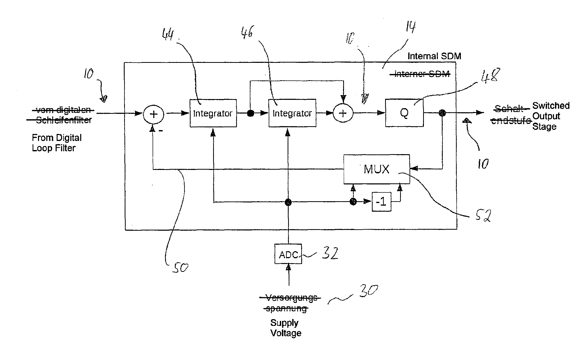
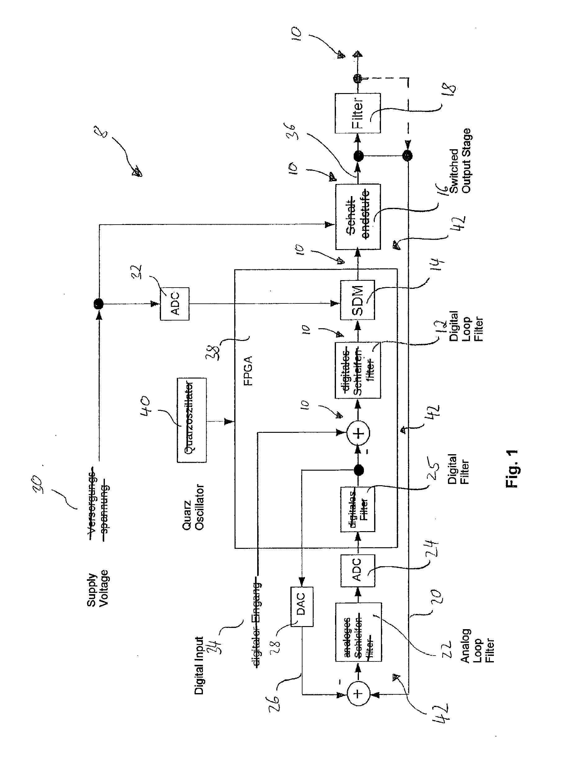
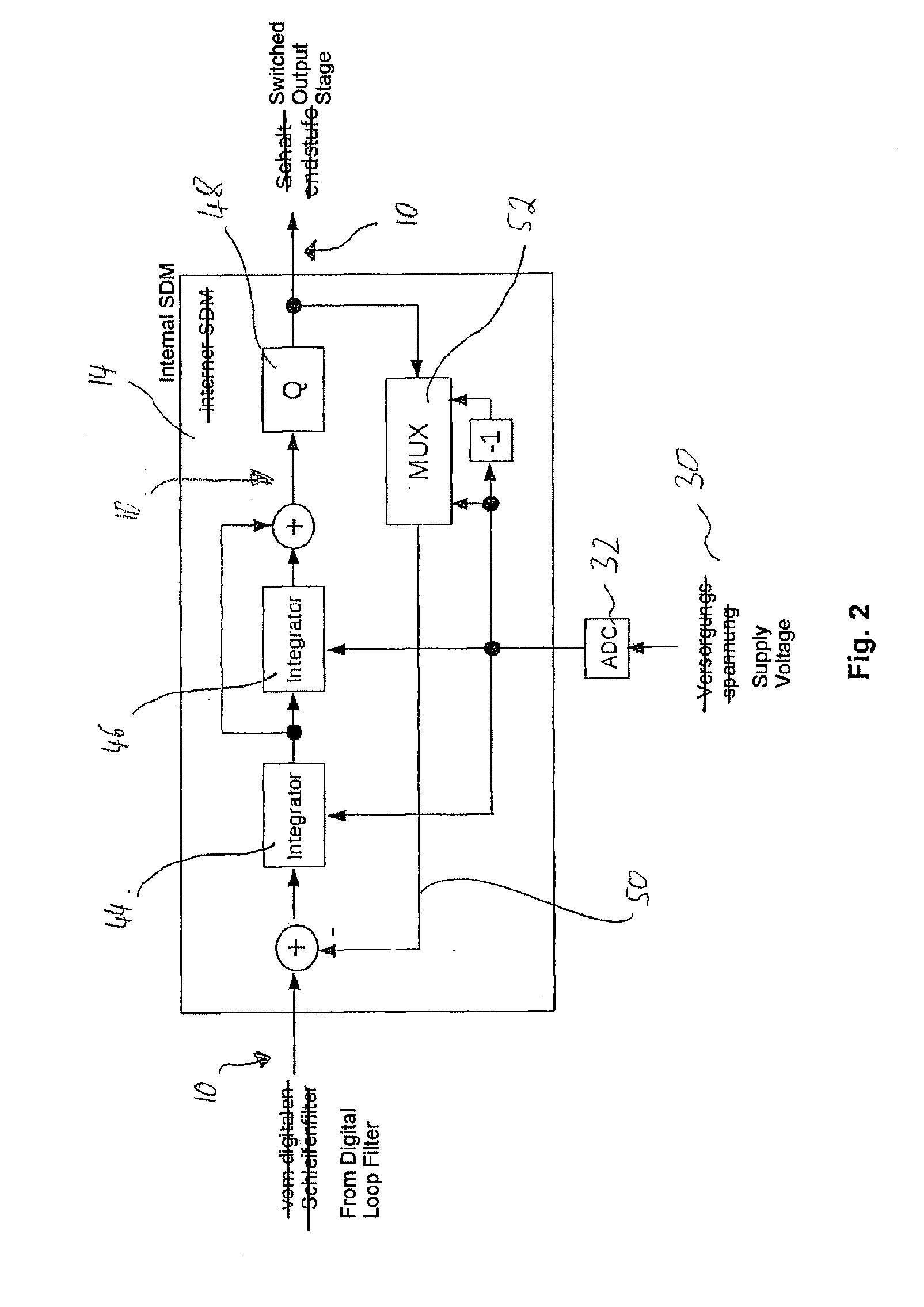
[0052]FIG. 1 shows an exemplary embodiment of the amplifier 8 according to the present invention. This includes a signal path 10 in which are consecutively arranged in forward or downstream direction: a digital loop filter 12, a digital sigma-delta-modulator 14, a switched output stage 16 and a filter 18. The switched output stage 16 is formed by an H-bridge. Furthermore, a negative feedback connection 20 is depicted, which at its input is connected with the signal path 10 between the switched output stage 16 and the filter 18 or alternatively with the signal path 10 behind the filter 18. Further, an analog loop filter 22, a first analog-digital converter 24 and a digital filter 25 are consecutively arranged in signal direction in the negative feedback connection 20. A digital-analog negative feedback connection 26 is connected, at its input, with the output of the digital filter 25 and, at its output, with the input of the analog loop filter 22. The digital-analog negative feedback...


PUM


Abstract

The amplifier according to the present invention serves to amplify an input signal to an output signal and includes a signal path and a negative feedback connection. The signal path includes a modulator which is suitable for receiving the input signal and for generating a switching signal in response to the received input signal. The signal path further includes a switched output stage, which is connected to a supply voltage, wherein the switched output stage contains a switch that is switched according to the switching signal generated by the modulator, wherein the switched output stage generates an output signal the amplitude of which depends on the supply voltage.

Description

[0001]pplicants claim, under 35 U.S.C. §§120 and 365, the benefit of priority of the filing date of May 3, 2013, of a Patent Cooperation Treaty patent application, copy attached, Serial Number PCT / EP2013 / 001323, filed on the aforementioned date, the entire contents of which are incorporated herein by reference, wherein Patent Cooperation Treaty patent application Serial Number PCT / EP2013 / 001323 was not published under PCT Article 21(2) in English.[0002]Applicants claim, under 35 U.S.C. §119, the benefit of priority of the filing date of May 24, 2012 of a German patent application, copy attached, Serial Number 10 2012 104 488.0 filed on the aforementioned date, the entire contents of which is incorporated herein by reference.FIELD OF THE INVENTION[0003]The present invention relates to the field of audio engineering. Specifically, it relates to a switched amplifier which is suitable for energy-efficient operation, as well as to a method for the energy-efficient amplification of audio ...

Claims


Application Information

Patent Timeline
IPC IPC(8): H03F3/217H04R3/00
CPCH03F3/217H03F3/2171H03F2200/504H03F2200/03H04R3/00H03F1/303H03F3/2175
Inventor KLUGBAUER-HEILMEIER, JOSEF
Owner HOCHSCHULE FUR ANGEWANDTE WISSENSCHAFTEN MUNCHEN
Learn More