Equipment unit, information processing system, information processing method, and program

a technology of information processing system and equipment, applied in the field of equipment units, information processing systems, information processing methods, programs, can solve the problems of reducing the ease of use of image forming apparatus, determining the cost of print jobs, and increasing the time required for printing, so as to reduce the amount of communication load

Inactive Publication Date: 2015-08-20
RICOH KK
View PDF5 Cites 3 Cited by
  • Summary
  • Abstract
  • Description
  • Claims
  • Application Information

AI Technical Summary

Benefits of technology

[0011]The embodiment of the present invention makes it possible to suppress an increased amount of communications load for distributing, to an equipment unit, a set of parameters for calculating an equipment use cost.

Problems solved by technology

In this case, one charging apparatus may determine a cost of the print job for the respective multiple image forming apparatuses which are used in parallel to perform upper limit management.
As a result, load is concentrated at the charging apparatus and the image forming apparatus places on hold a response to an inquiry on whether printing is possible, causing a likelihood of an increased time required for printing (in other words, causing a likelihood in lowered ease of use of the image forming apparatus.)
However, distributing the set of parameters every time updating is made could cause the communications load for distributing the set of parameters to increase.

Method used


Image

  • Equipment unit, information processing system, information processing method, and program
  • Equipment unit, information processing system, information processing method, and program
  • Equipment unit, information processing system, information processing method, and program

Examples


Embodiment Construction

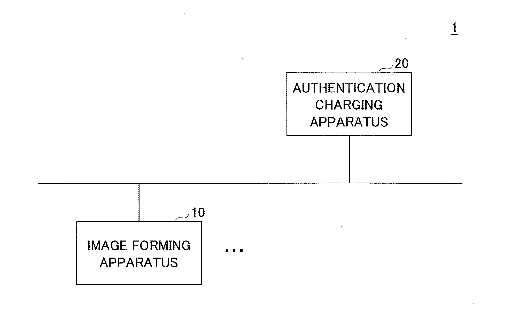
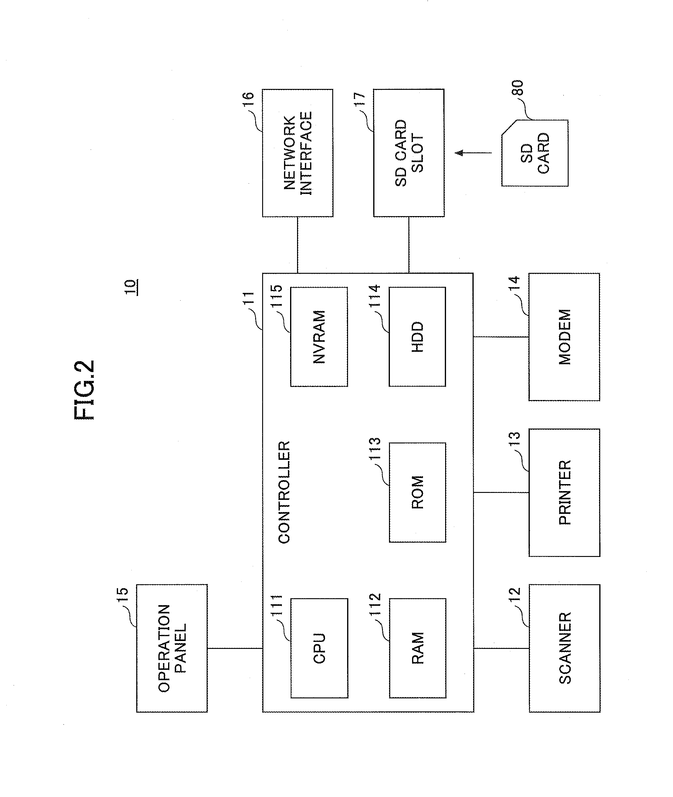
[0026]Below, an embodiment of the present invention is explained based on the drawings. FIG. 1 is a diagram illustrating an exemplary configuration of a printing system according to an embodiment of the present invention. In a printing system 1 shown in FIG. 1, at least one image forming apparatus 10 and an authentication charging apparatus 20 are communicatively connected via a network such as a LAN (local area network), the Internet, etc.

[0027]The image forming apparatus 10 is an equipment unit which has a function of printing print data which are registered in advance by a logged-in user. The image forming apparatus 10 also includes a function (below-called “upper-limit management function” of restricting use of the image forming apparatus 10 by the user to within a range of an upper limit value set in advance.

[0028]The authentication charging apparatus 20 is a computer which manages information for authenticating the respective users with a privilege to use the image forming app...


PUM


Abstract

An equipment unit is disclosed, including a first obtaining unit which obtains first identification information for a parameter set for calculating a use amount of the equipment unit; a comparison unit which compares the first identification information and second identification information for a parameter set for calculating a use amount of the equipment unit; a second obtaining unit which obtains information on a difference between the parameter set related to the first identification information and the parameter set stored in the equipment unit when the first identification information and the second identification information differ; and a control unit which calculates an amount of use of the equipment unit based on the parameter set stored in the equipment unit, and the information on the difference and controls the use of the equipment unit by the user.

Description

TECHNICAL FIELD[0001]The present invention relates to equipment units, information processing systems, information processing methods, and programs.BACKGROUND ART[0002]An upper limit management function is used in image forming apparatuses. The upper limit management function is a function such that execution of printing is permitted for the respective users within a range of an upper limit value for the respective users. Examples of the image forming apparatuses which include the upper limit management function include an image forming apparatus connected to a coin rack which is installed in a supermarket, a convenience store, etc. In such an image forming apparatus, execution of printing is restricted to within a range of an amount dropped into the coin rack (below-called “a charging apparatus”).PATENT DOCUMENT [0003]Patent Document 1: JP2011-150531A[0004]In the above-described example, one charging apparatus is connected to one image forming apparatus. Therefore, the charging app...

Claims


Application Information

Patent Timeline
Patent Type & Authority Applications(United States)
IPC IPC(8): H04N1/00G06Q30/02
CPCH04N1/00925G06Q30/0283H04N1/00204H04N1/00034H04N2201/0094H04N1/00068H04N1/00082H04N1/00832H04N1/00877H04N1/00061H04N1/00015H04N1/34H04N2201/0039
Inventor OHARA, KAZUKI
Owner RICOH KK
Why Eureka
Try Eureka