
Protective helmet

a protective helmet and helmet technology, applied in the field of protective helmets, can solve the problems of high cost, complex and economically unfavorable systems, and user discomfort, and achieve the effects of reducing the retraction of the helmet, and managing the thickness

Active Publication Date: 2015-08-27
FERRANDO GARCIA CARLOS +2
View PDF16 Cites 5 Cited by
  • Summary
  • Abstract
  • Description
  • Claims
  • Application Information

AI Technical Summary

Benefits of technology

The present invention is a protective helmet for sports activities that require a high level of safety, such as climbing, skating, and skiing. The helmet has a unique design that allows for a retracted position, which is compact and comfortable to transport without wearing it. The helmet has a telescopically coupled inner, intermediate, and outer base components that move in relation to each other, creating a space to protect the user's head. The helmet is designed to be efficient, economical, and easy to use. The technical effect of the invention is to provide a protective helmet for sports activities that reduces the volume and discomfort of traditional helmets, while still providing safety standards.

Problems solved by technology

However, there is a negative aspect common to all helmets, which is still a real drawback, and this is their extraordinary volume, causing great discomfort to the user when the helmet is transported without wearing it.
The currently existing solutions are based on systems which are complex and economically not very feasible.
The second case is document KR200110012557A, in which the folding / retraction of the helmet is significant enough, although the retraction system by means of hinges causes it to have a high cost.

Method used


Image

  • Protective helmet
  • Protective helmet
  • Protective helmet

Examples


first embodiment

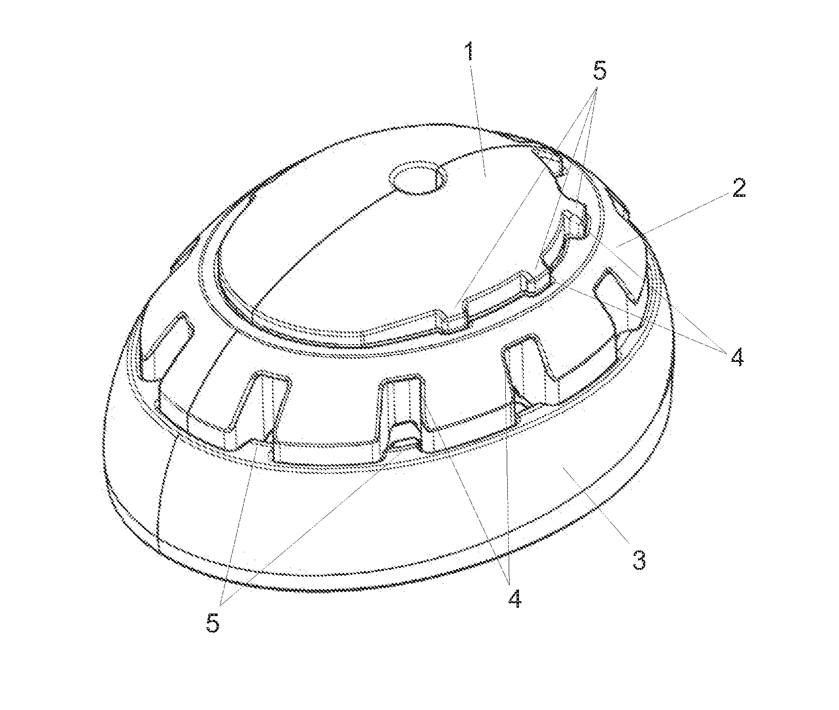
[0020]FIG. 1 depicts a perspective view of the helmet in its deployed position.

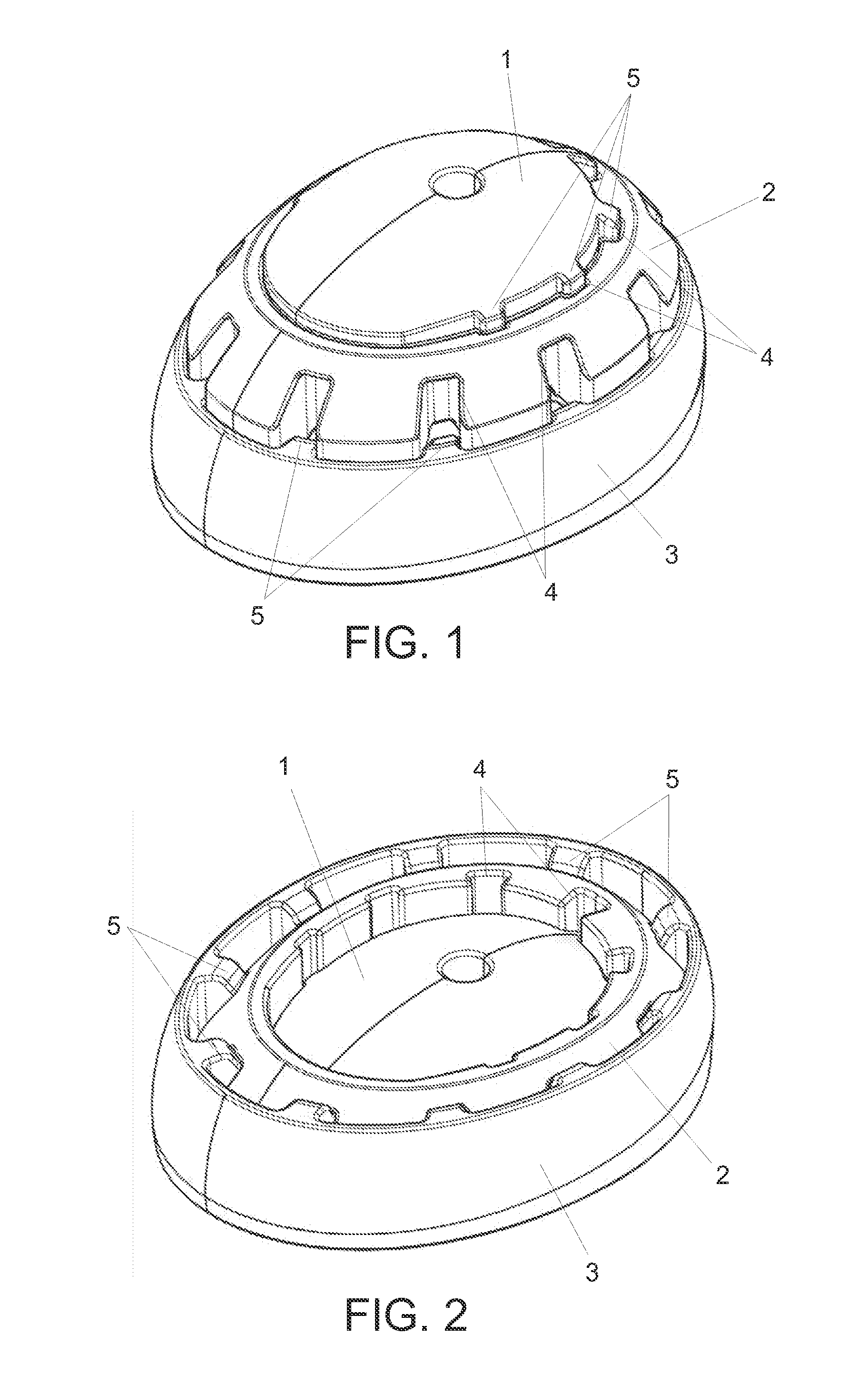
[0021]FIG. 2 depicts a perspective view of the first embodiment of the helmet in its retracted position.

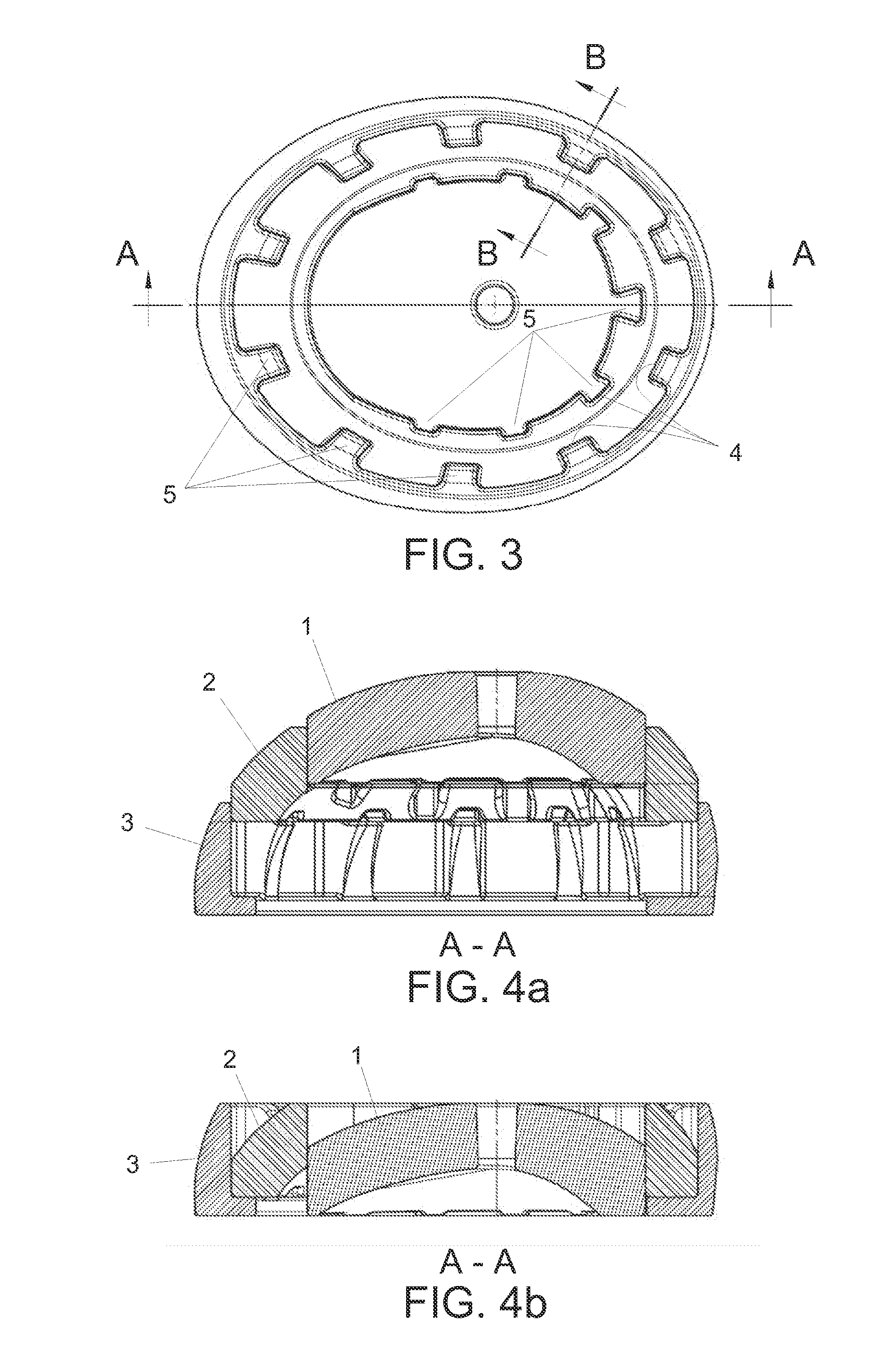
[0022]FIG. 3 depicts a plan view of the first embodiment of the helmet in its deployed position.

[0023]FIGS. 4a and 4b depict cross-section views of the first embodiment of the helmet along plane A-A in its deployed and retracted positions respectively.

[0024]FIGS. 5a and 5b depict cross-section views of the first embodiment of the helmet along plane B-B in its deployed and retracted positions respectively.

second embodiment

[0025]FIG. 6 depicts a perspective view of the helmet in its deployed position.

[0026]FIG. 7 depicts a perspective view of the second embodiment of the helmet in its retracted position.

[0027]FIG. 8 depicts a plan view of the second embodiment of the helmet in its deployed position.

[0028]FIGS. 9a and 9b depict cross-section views of the second embodiment of the helmet along plane CC in its deployed and retracted positions respectively.

[0029]A list of the references used in the figures is provided below:[0030]1. Inner component.[0031]2. Intermediate component.[0032]3. Outer base component.[0033]4. Female axial guide elements.[0034]5. Male axial guide elements.[0035]6. Intermediate component upper tabs.[0036]7. Intermediate component lower tabs.[0037]8. Inner edge portion of the outer component.[0038]9. Inner component angular seats.[0039]10. Hinged portions.

DETAILED DESCRIPTION

[0040]The description of two forms of preferred embodiments of the invention is made below, referring to the r...


PUM


Abstract

The invention relates to a protective helmet for protecting the head of a user, characterized in that it comprises an enveloping structure consisting of an inner component (1), at least one intermediate component (2) and an outer base component (3) having an annular configuration, where said components (1, 2, 3) are coupled one inside the other, can move in relation to each other from a retracted position to a deployed position and vice versa, and create a space, in a deployed position, corresponding to the part of the user's head that is inside the helmet.

Description

OBJECT OF THE INVENTION[0001]The present invention relates to a protective helmet for practicing sports activities with a certain type of risk of falling and in which a high level of protection is required, such as climbing, skating, skiing, etc., and in particular, the use of a bicycle.[0002]It is of special application in the field of the sports industry.TECHNICAL PROBLEM TO BE SOLVED AND BACKGROUND OF THE INVENTION[0003]In the current state of the art a variety of methods are known related to obtaining greater levels of safety for activities, in particular sports activities, in which wearing a helmet is increasingly often required for avoiding or at least reducing the consequences of a fall or a crash.[0004]This is of special application in the practice of sports activities with a certain type of danger for the risk of falling due to the height or speed reached, such as climbing, skating or skiing, and more particularly, in the field of cycling.[0005]Likewise, it must be taken in...

Claims


Application Information

Patent Timeline
Patent Type & Authority Applications(United States)
IPC IPC(8): A42B3/32
CPCA42B3/322
Inventor FERRANDO GARCIA, CARLOSMIGUEL MARTIN, DAVIDCERDA NAVARRO, RAFAEL
Owner FERRANDO GARCIA CARLOS
Learn More