Custom reduction splint for edentulous patients

a splint and edentulous patient technology, applied in the field of oral splints, can solve the problems of missing teeth, longening of the opposing tooth, and gaps between teeth of partial edentulous patients, and achieve the effect of maintaining fracture alignment and accelerating the availability of splints for operative us

Active Publication Date: 2015-08-27
UNIV OF SOUTH FLORIDA
View PDF12 Cites 18 Cited by
  • Summary
  • Abstract
  • Description
  • Claims
  • Application Information

AI Technical Summary

Benefits of technology

[0047]It is an object of an embodiment of the current invention to provide a device designed with consideration of fracture reduction and patient safety, along with preservation postoperatively to assist in maintenance of fracture alignment.
[0048]It is an object of an embodiment of the current invention to utilize a facial bones CT scan and 3D printing, thus significantly expediting the availability of the splint for operative use.

Problems solved by technology

Partially edentulous patients often have gaps between teeth from missing teeth.
Any areas of missing teeth can lead to lengthening of the opposing tooth, as it does not have proper occlusal contact.
For example, if a mandibular lateral incisor is absent, the opposing maxillary dentition will lack normal occlusal contact, which can result in lengthening of the opposing maxillary tooth.
This further adds to any height discrepancies between teeth and leads to areas of non-contact between the tooth and splint, ultimately causing fracture malreduction.
As such, Cartledge fails to provide either equally distributed contact or stability of fracture reduction.
Further, the splint of Cartledge does not address the occlusion of the patient.
If the splint rests in contact with dentition, it interferes with proper occlusion, which is the primary objective in fracture reduction.
If the splint rests in contact with the gingiva directly, as in the case of an edentulous patient, then the proper distance is not maintained for the patient to wear their denture appliance postoperatively.
The device does not assist in reduction of mandible fractures of the angle, ramus, condyle or coronoid.
However, this methodology is quite complex and involves multiple steps, including separate dental trays, dental modeling, and merging of the facial bone CT with dental CT data.
This can become very time-consuming and inefficient in the fabrication of the splint.
This device also does not address fracture reduction but rather is for craniofacial and maxillofacial deformities requiring osteotomies, which is not used for fracture reduction.
The device also does not address postoperative maintenance of the surgical splint.
However, this device is not personalized for individual patient and also requires bonding to the patients teeth.
As it requires bonding to teeth, the device cannot be used in edentulous patients.
Furthermore, the postoperative stability of the device is limited by the relative strength of the bonding agent used.
However, as indicated, the device is incapable of assisting with fracture reduction and is constructed of a thermoformable tray.
The device also addresses orthognathic surgical procedures, rather than reduction of maxillary or mandibular fractures and is incapable of performing as such.
The device can only be used in patients with dentition and thus cannot be applied to partially or completely edentulous patients.
The device utilizes plaster dental modeling for formation of the acrylic splint, which can hinder the availability of the splint for operative use.
The device further requires dentition to maintain fracture stability, and thus does not have application to partially or completely edentulous patients.
Thus, in an adult fracture, it is doubtful that the acrylic splint would reduce the fracture and maintain postoperative alignment.
Generally, in difficult patient populations, such as those with edentulism or partial edentulism, there are very limited options for maxillomandibular fixation, and none provide stable reduction of fractures, including the foregoing devices and methodologies discussed.
In many cases, the dentures are worn down and thus are not positioned where the patient's jaws should be aligned.
As a result, the patient's jaw may have collapsed to an extent.
This destroys the dentures for any future use and forces the patient to purchase a new set of expensive dentures.
Furthermore, where a definition or use of a term in a reference, which is incorporated by reference herein, is inconsistent or contrary to the definition of that term provided herein, the definition of that term provided herein applies and the definition of that term in the reference does not apply.

Method used


Image

  • Custom reduction splint for edentulous patients
  • Custom reduction splint for edentulous patients
  • Custom reduction splint for edentulous patients

Examples


Embodiment Construction

[0100]In the following detailed description of the preferred embodiments, reference is made to the accompanying drawings, which form a part thereof, and within which are shown by way of illustration specific embodiments by which the invention may be practiced. It is to be understood that other embodiments may be utilized and structural changes may be made without departing from the scope of the invention.

[0101]As used in this specification and the appended claims, the singular forms “a”, “an”, and “the” include plural referents unless the content clearly dictates otherwise. As used in this specification and the appended claims, the term “or” is generally employed in its sense including “and / or” unless the context clearly dictates otherwise.

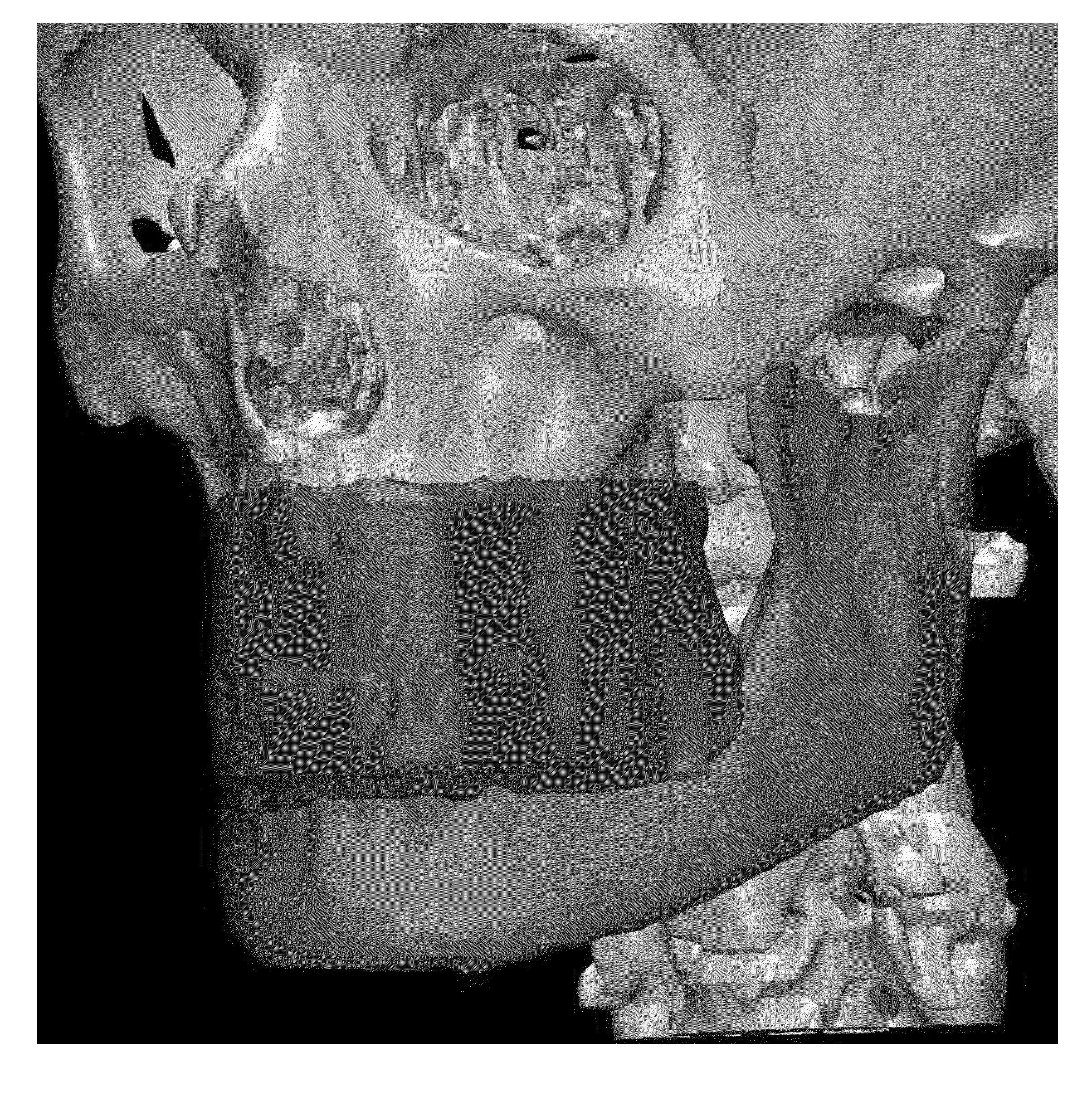
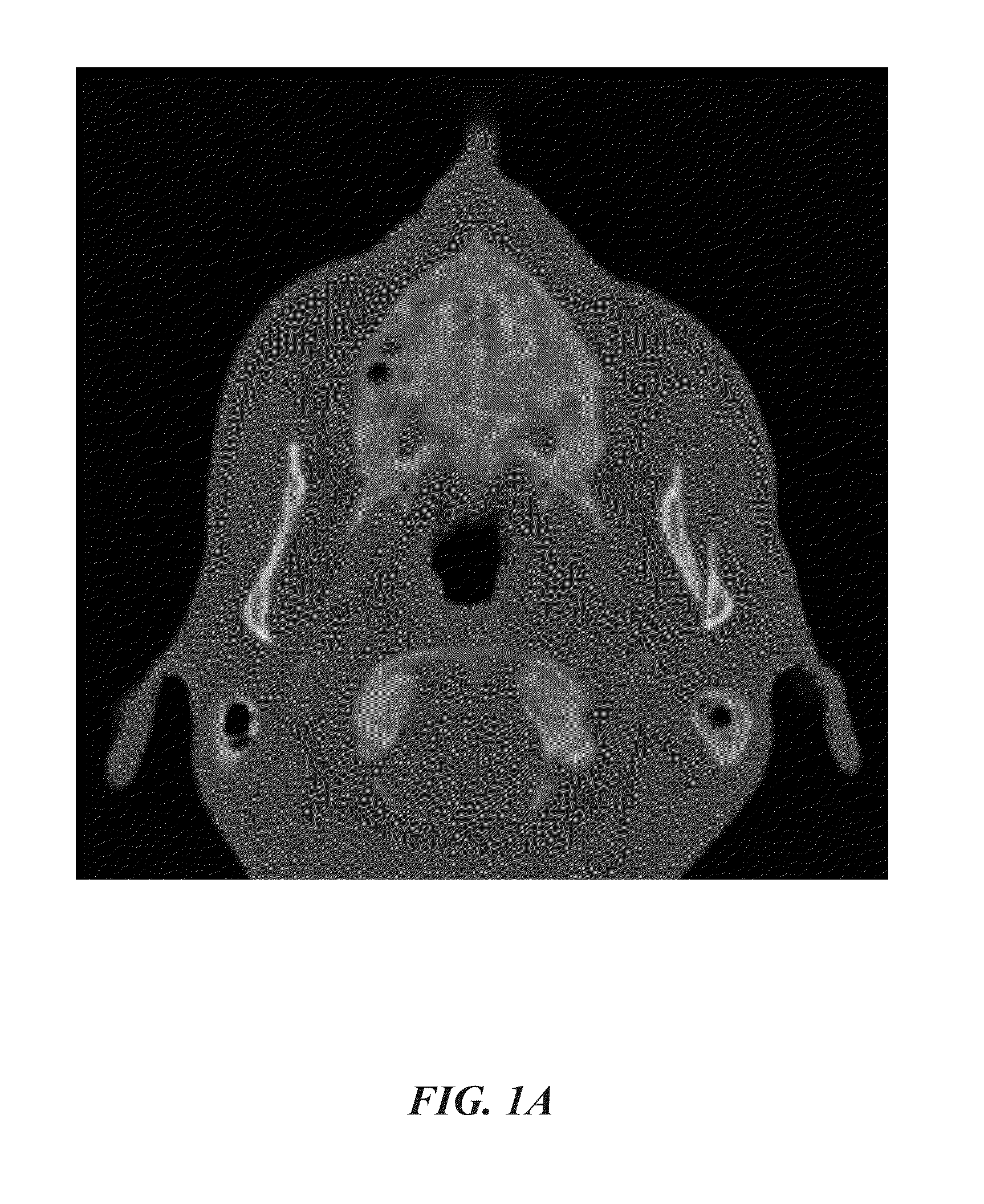
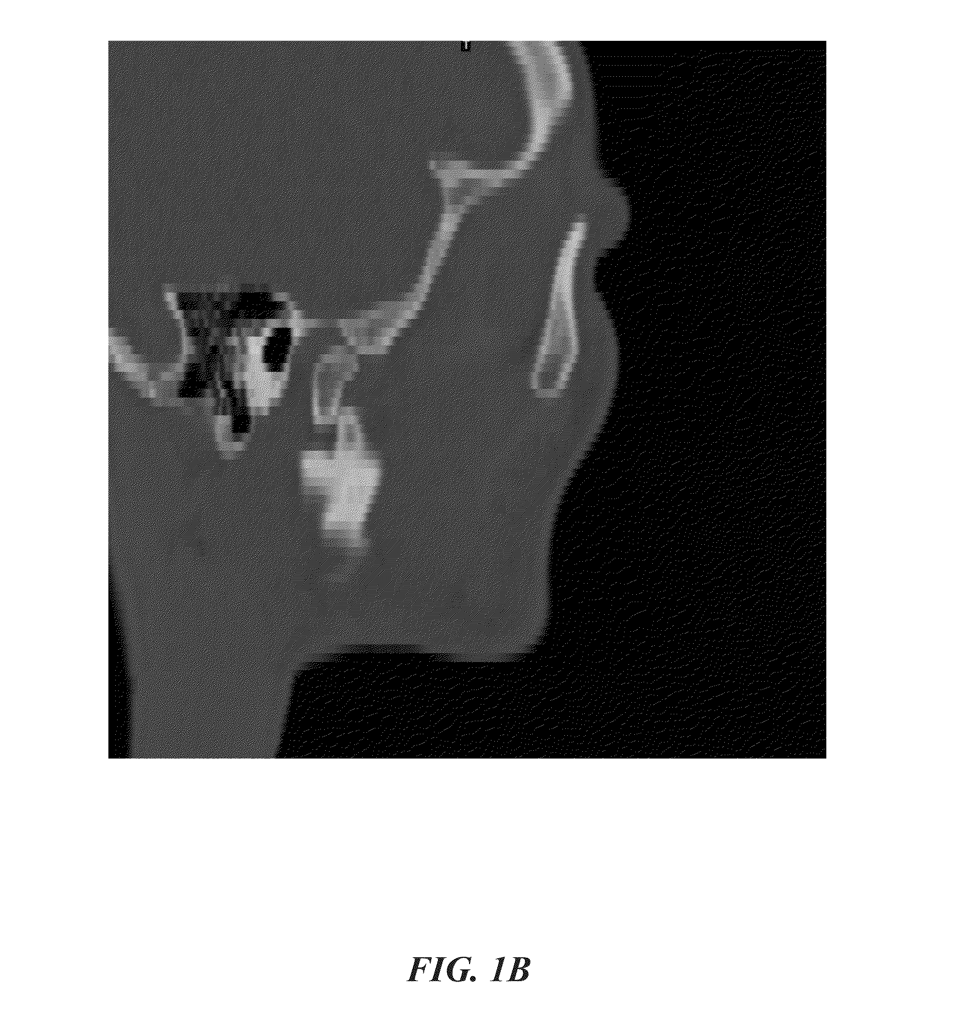
[0102]In an embodiment, the current invention is a methodology and / or device for a custom oral splint that is operatively secured to the maxilla and mandible to assist in fracture reduction. The methodology / device further provide maintenance of re...


PUM


Abstract

A custom oral splint that is operatively secured to the maxilla and mandible of a subject/patient to assist in reduction and provide maintenance of reduction of maxillary and mandibular fractures in the edentulous or partially edentulous subject/patient. In this difficult patient population, there are very limited options for maxillomandibular fixation, and none provide stable reduction of fractures. The novel device minimizes operative time and equipment, as well as offers the ability to transition the patient from rigid fixation to elastics postoperatively. The novel device is custom-designed for each patient's degree of bone atrophy, ensuring a high quality, and effective product.

Description

CROSS-REFERENCE TO RELATED APPLICATIONS[0001]This nonprovisional application is a continuation of and claims priority to U.S. Provisional Application No. 61 / 943,636, entitled “Custom Reduction Splint for Edentulous and Partially Edentulous Patients”, filed Feb. 24, 2014 by the same inventors, the entirety of which is incorporated herein by reference.BACKGROUND OF THE INVENTION[0002]1. Field of the Invention[0003]This invention relates, generally, to oral splints. More specifically, it relates to the reduction and maintenance of reduction in mandible and / or maxilla fractures of edentulous or partially edentulous patients.[0004]2. Brief Description of the Prior Art[0005]Oral splints are commonly known in the art, including those utilized for fixation of the jaw during recovery from mandibular or maxillary fractures. For example, U.S. Pat. No. 6,227,861 to Cartledge et al. discusses a pre-formed mandible splint and a method of aligning and stabilizing a fractured mandible with such a s...

Claims


Application Information

Patent Timeline
Patent Type & Authority Applications(United States)
IPC IPC(8): A61F5/058A61B6/03G06T7/00A61C5/14A61M1/00A61B6/14A61B5/055
CPCA61F5/05891A61B6/14A61B6/032A61B6/037A61B5/055G06T2210/41A61M1/0023G06T7/00A61M2207/10G06T2207/30036A61C5/14A61C5/007A61C9/0053A61C13/0004A61C17/08G06T3/0068G06T17/20G06T2200/08G16H20/40
Inventor DECKER, SUMMER JOYFORD, JONATHAN MICHAELCHING, JESSICA ALLEN
Owner UNIV OF SOUTH FLORIDA
Why Eureka
Try Eureka