Inhalator

a technology of inhalator and inhalation chamber, which is applied in the field of inhalators, can solve the problems of inefficient and incomplete spending of some substances, inefficient use of stored substances, and air can sometimes interact with substances in an unwanted way, and achieve the effect of realizing the feeling of holding and smoking

a technology of inhalator and inhalation chamber, which is applied in the field of inhalators, can solve the problems of inefficient and incomplete spending of some substances, inefficient use of stored substances, and air can sometimes interact with substances in an unwanted way, and achieve the effect of realizing the feeling of holding and smoking

US20150238723A1Inactive Publication Date: 2015-08-27LK INVESTMENT

Image

  • Inhalator
  • Inhalator
  • Inhalator

Examples


Embodiment Construction

[0044]In the following detailed description of an inhalator according to the invention will be described by the preferred embodiments.

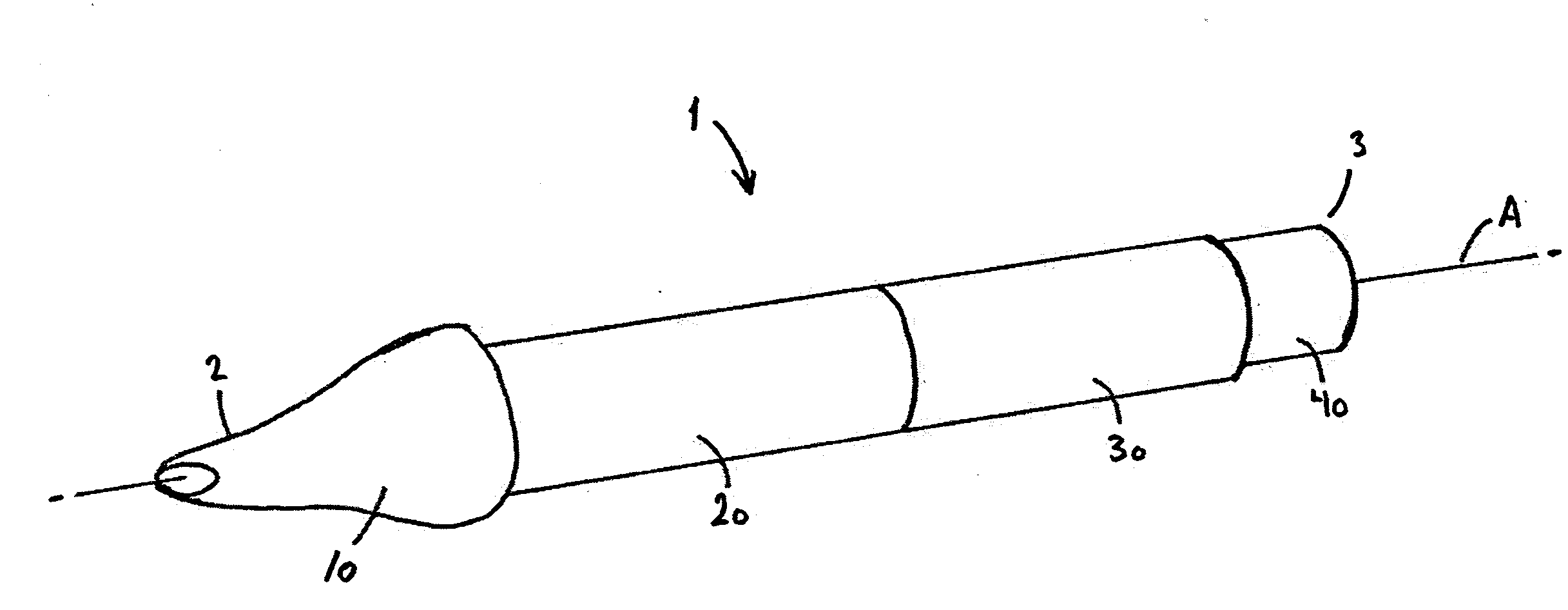
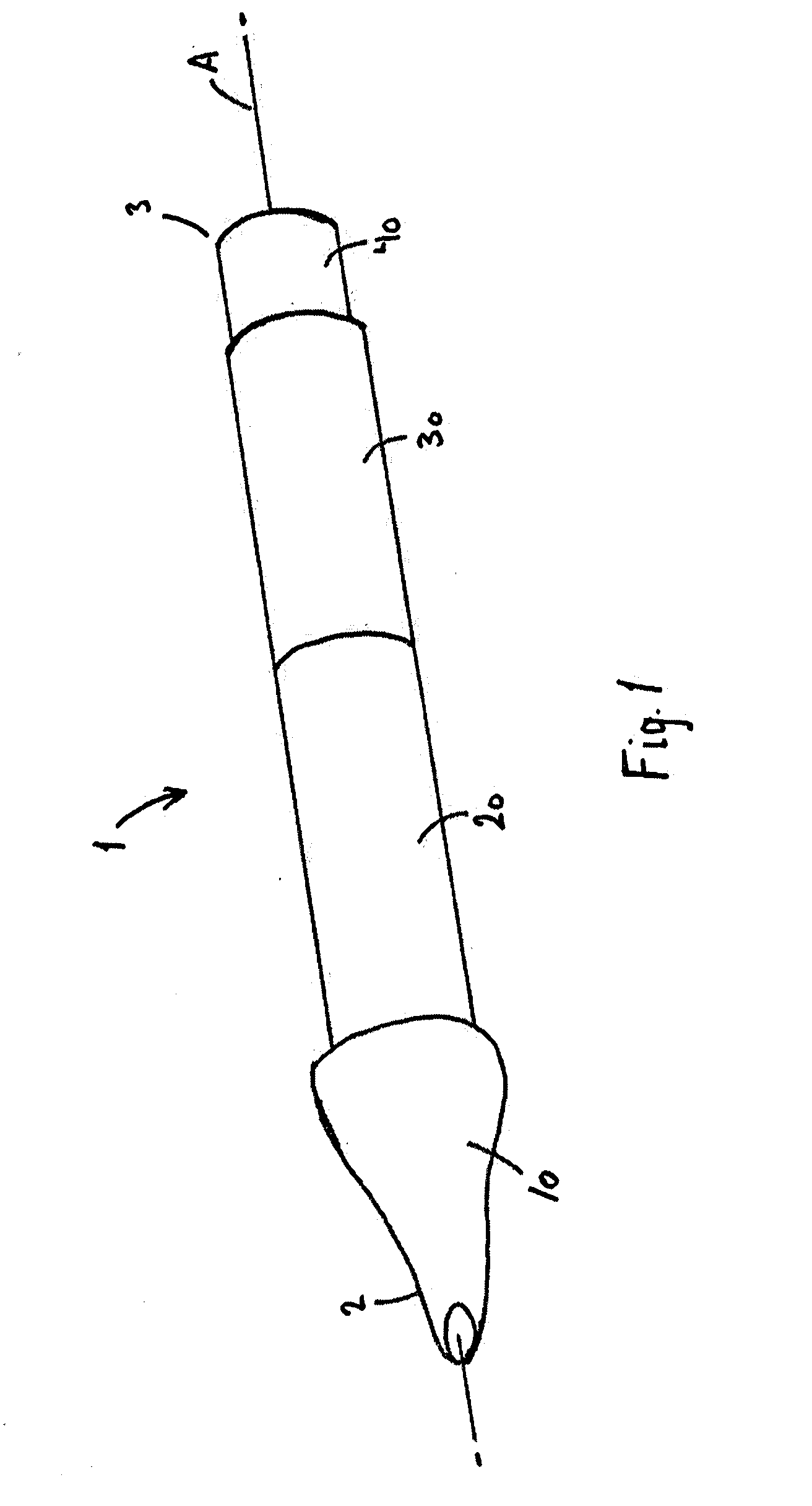
[0045]FIG. 1 shows in an inhalator 1 comprising an elongated tubular, e.g. cylindrical, housing. The elongate tubular housing has a proximal end 2 and a distal end 3, and a longitudinal axis A. By proximal end is meant the end that is closest to a user of the inhalator during use and by distal end is meant the end that faces away from the user during use. At the proximal end 2, the inhalator 1 may as shown comprise a user interface part 10 configured for allowing the user to inhale one or more substances enclosed in the inhalator either through a mouth or a nose of a user. Thus the user interface part 10 may be a mouthpiece or a part specially adapted for interaction with nostrils of the nose of a user.

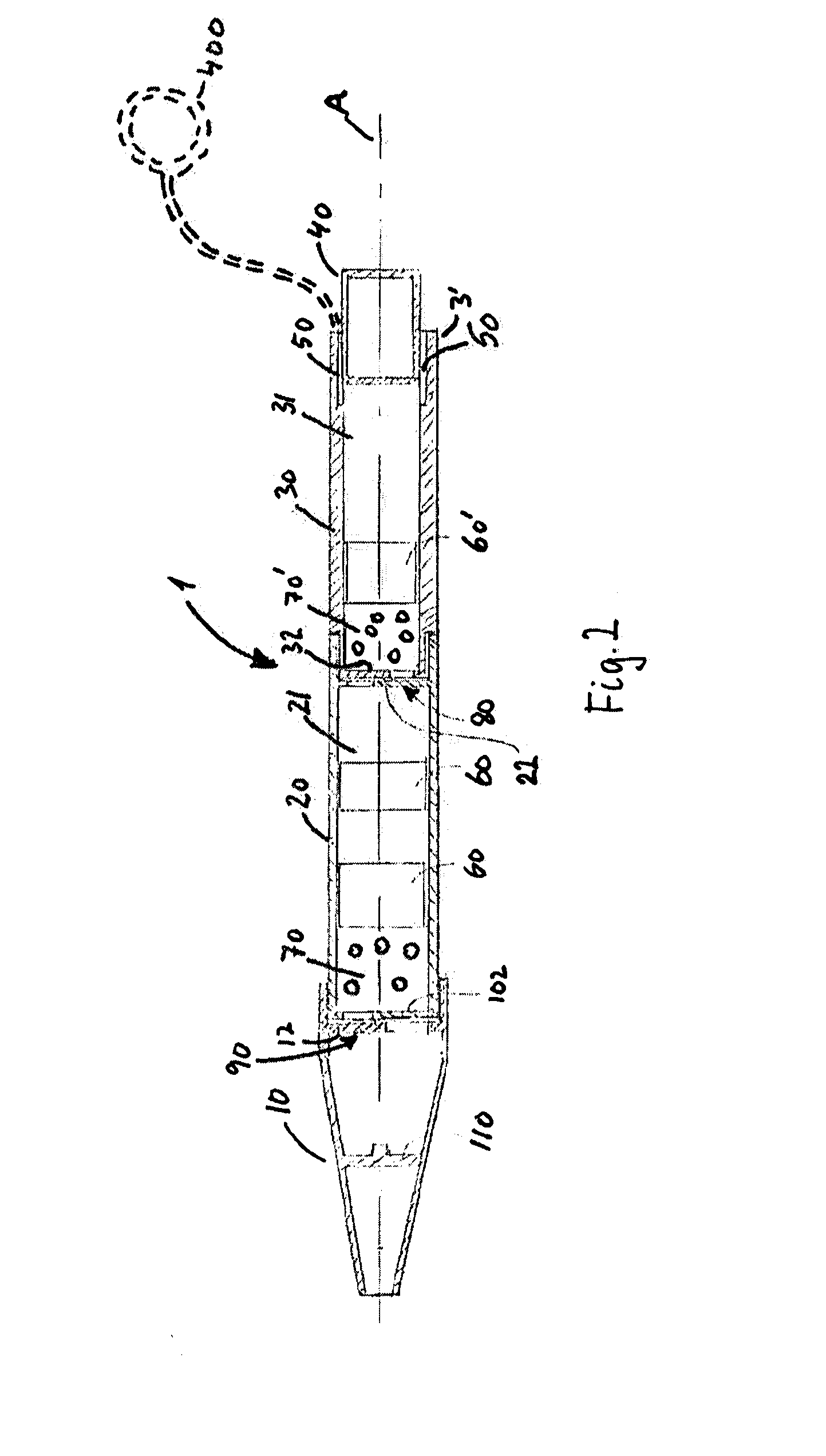
[0046]The inhalator 1 further comprises a first and a second tubular part 20, 30 arranged in extension of each other. The first tubular part 20 defines...


PUM


Abstract

An inhalator (1) comprisinga first compartment (21) confining an active compound;a second chamber (31) containing a transporter; andan activation part (40) configured for regulating an air flow through the inhalator (1), and arranged at a distal end the second compartment (31),characterized in that the first compartment (21) is arranged between a user interface part (10) and the second compartment (31) such that when a user sucks air through the inhalator (1), the transporter is drawn from the second compartment (31) through the first compartment (21), whereby the active compound is captured by the transporter and flows into the user interface part (10) and the user.

Description

BACKGROUND OF THE INVENTION[0001]The present invention relates to an improved inhalator, also called an inhaler. The inhalator may allow two or more substances to be packed such that they do not interact until the inhalator is brought to an operative state.[0002]Often there is a need to store two or more reactive substances together but separated, e.g. two component glue, penicillin and water or interactive substances. When mixed, such substances will often initiate a reaction.[0003]It is known that reactive substances when mixed can degrade each other by oxidation, reduction or by forming combination products. Likewise, the presence of air can sometimes interact with substances in an unwanted way. In connection with inhalators where two or more substances need to be mixed and inhaled it is often necessary to store the substances separately prior to inhalation.[0004]EP 2002856 discloses an inhalator comprising a number of elastic bodies or spheres elastically restrained in a duct. P...

Claims


Application Information

Patent Timeline
27 Aug 2015
Publication
US20150238723A1
IPC
A61M16/14; A61M16/20; A61M15/00; A24F42/20; A24F42/60
CPC
A61M16/14; A61M16/20; A61M15/0091; A61M15/0021; A61M15/06; A61M15/0003; A61M15/002; A24F42/20
Inventors
KNUDSEN, CARSTEN LEONHARD