
Sprocket and chain transmission mechanism

a transmission mechanism and chain technology, applied in the direction of gearing, gearing elements, hoisting equipment, etc., can solve the problems of increasing the pitch of the chain, the change of speed, and the increase of the meshing sound, so as to increase the correspondence margin of the seating position, increase the pitch, and increase the elongation of the chain

Active Publication Date: 2015-08-27
TSUBAKIMOTO CHAIN CO
View PDF8 Cites 2 Cited by
  • Summary
  • Abstract
  • Description
  • Claims
  • Application Information

AI Technical Summary

Benefits of technology

The patent involves a chain transmission mechanism that reduces speed changes and vabilitites caused by the movement of a roller when it comes into contact with a sprocket. However, the mechanism does not account for changes in the position of the roller when it comes into contact with the sprocket, which can affect the roller's seat position on the bottom land portion.

Problems solved by technology

However, although the sprockets of the well-known chain transmission mechanisms effectively decrease changes in speed of the roller chain caused by the polygonal movement and reduce the vibrations, they do not take into account that the elongation of the chain changes the position in which the roller initially comes into contact with the sprocket and the seat position when the roller sits on the bottom land portion.
Actually, the pitch of the chain increases due to the elongation caused by tension and also elongation caused by changes with time and wear of sliding parts.
This problem is created not only by the standard sprocket 500, but also by the aforementioned well-known non-standard sprockets, and it results in increased meshing sound.
Further, such impacts cause wear of meshing portions of the chain or sprocket and also generate large forces acting upon other sliding parts of the chain, cause wear, and shorten the service life of the chain and sprocket.

Method used


Image

  • Sprocket and chain transmission mechanism
  • Sprocket and chain transmission mechanism
  • Sprocket and chain transmission mechanism

Examples


example 1

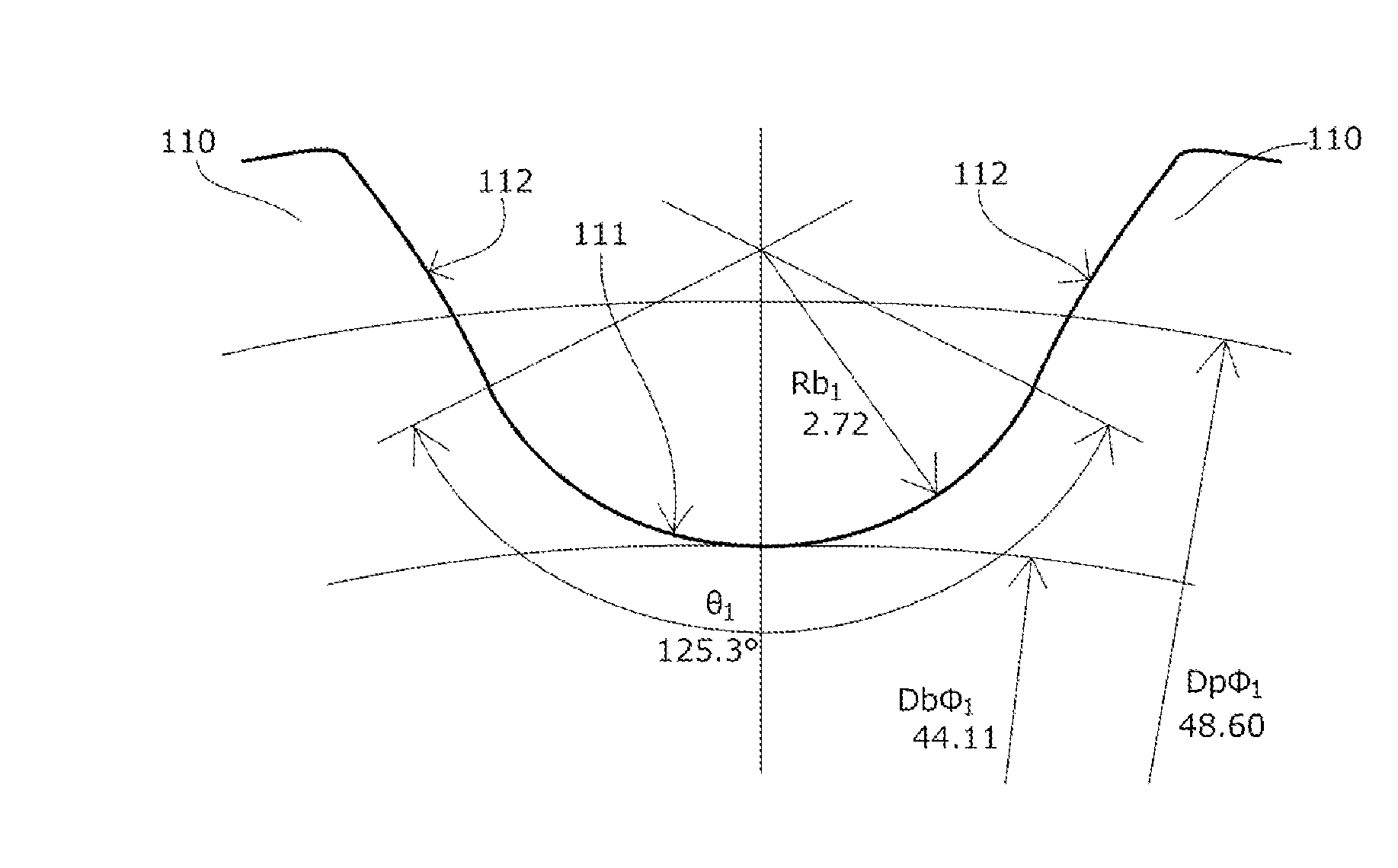
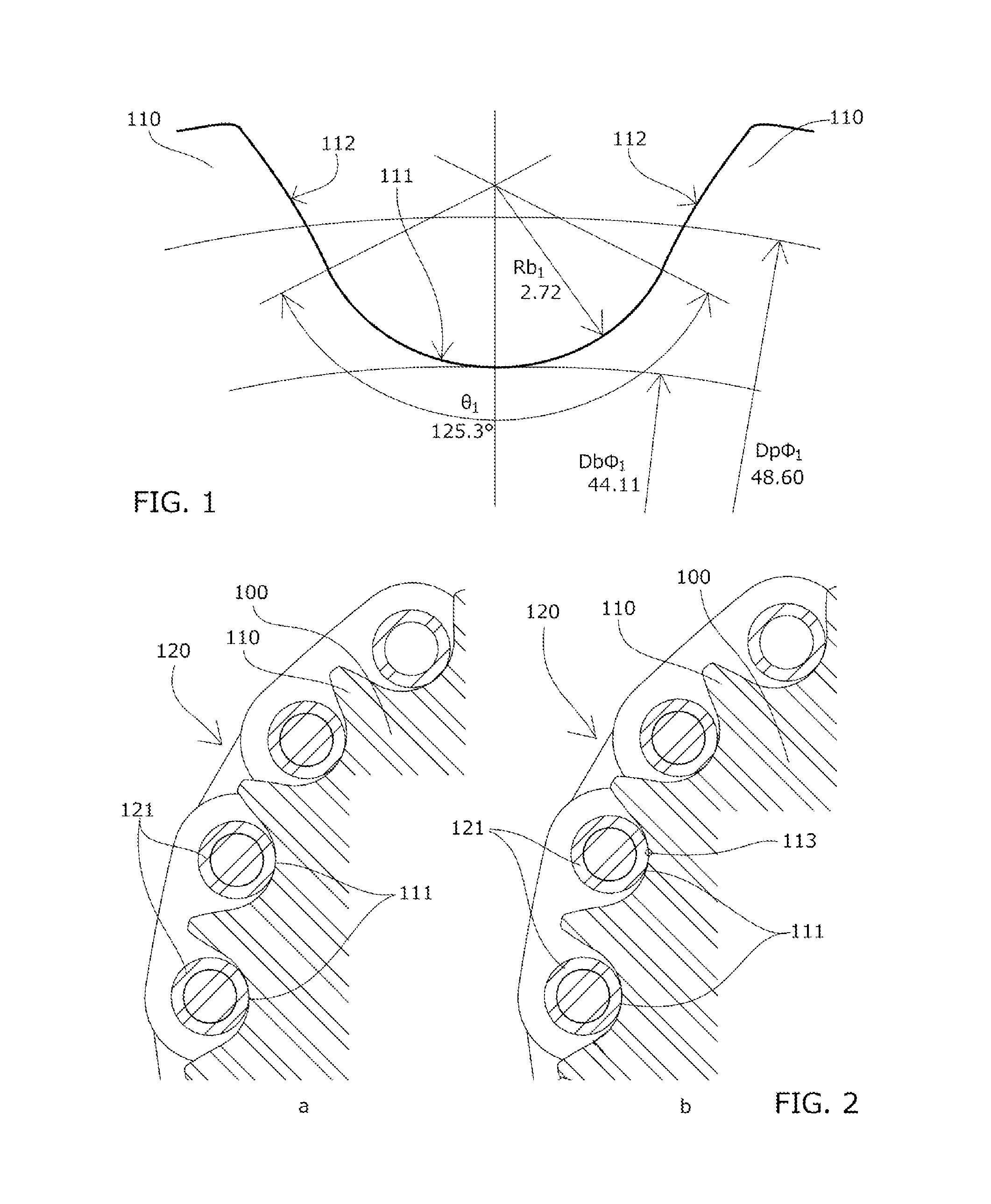
[0033]A sprocket 100 which is the first embodiment of the sprocket and chain transmission mechanism in accordance with the present invention is designed to mesh with a roller chain 120 with a roller diameter of φr1=4.49 mm. As depicted in FIG. 1, the sprocket has the following specifications.

[0034]Pitch diameter: Dpφ1=48.60 mm

[0035]Bottom land portion arc radius: Rb1=2.72 mm

[0036]Bottom land portion arc angle: θ1=125.3°

[0037]Root circle diameter: Dpφ1=44.11 mm

[0038]Number of teeth in the sprocket: z1=19

[0039]The “roller” and “roller chain” may be “bush” and “bush chain” (same hereinbelow).

[0040]When the roller chain 120 is not elongated at all, as shown in FIG. 2A, all of the rollers 121 of the roller chain 120 mesh with substantially central sections of bottom land portions 111 of the sprocket 100, in the same manner as in a standard sprocket 500.

[0041]Where the pitch of the roller chain 120 has increased due to elongation under tension, elongation caused by changes with time, and ...

example 2

[0050]A sprocket 200 which is the second embodiment of the sprocket and chain transmission mechanism in accordance with the present invention is designed to mesh with a roller chain with a roller diameter of φr1=4.49 mm. As depicted in FIG. 5, the sprocket has the following specifications.

[0051]Pitch diameter: Dpφ2=48.60 mm

[0052]Bottom land portion arc radius: Rb2=2.72 mm

[0053]Bottom land portion arc angle: θ2=125.3°

[0054]Root circle diameter: Dbφ2=44.26 mm

[0055]Number of teeth in the sprocket: z2=19

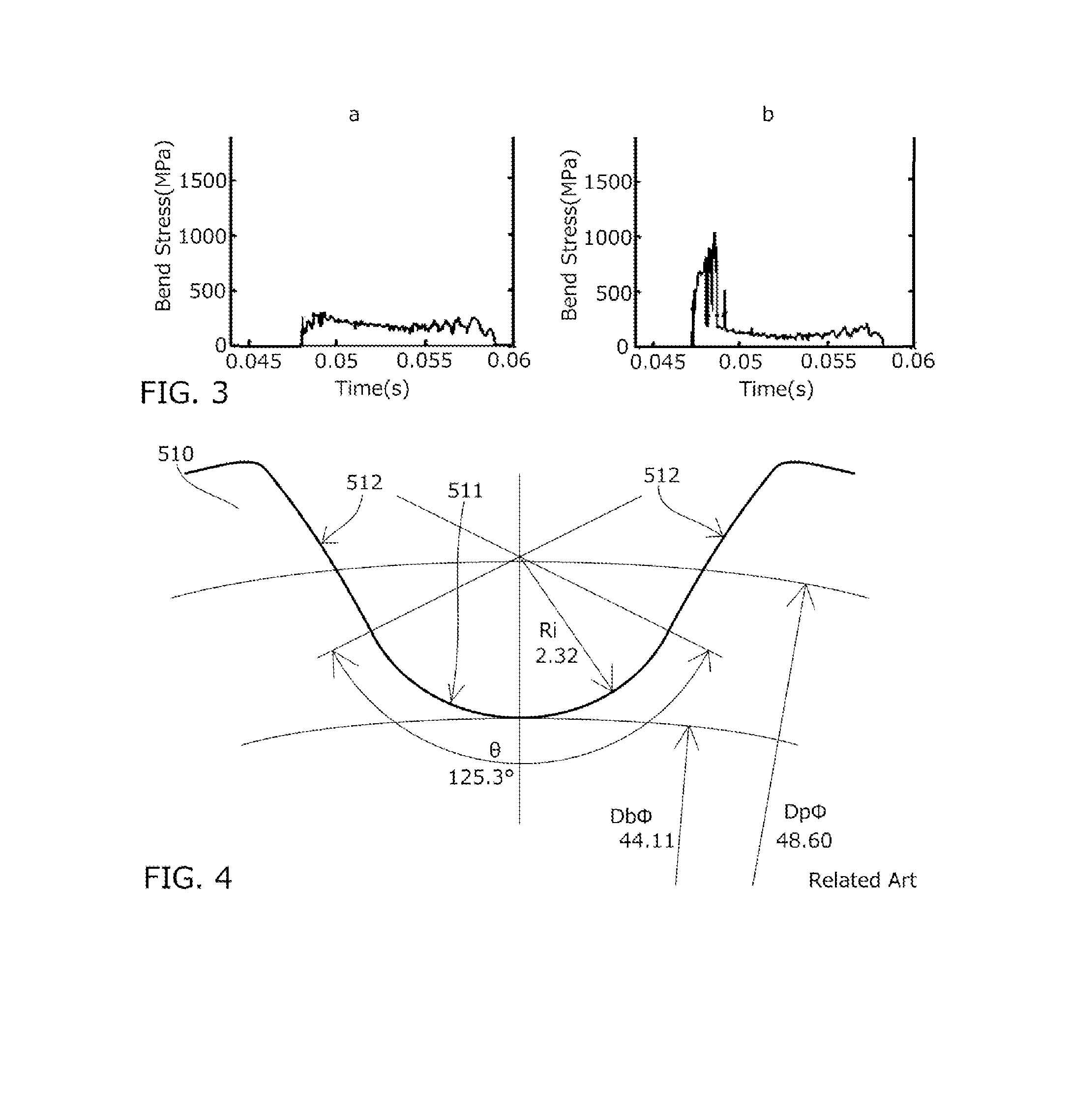
[0056]The specifications of the sprocket 200 of the present embodiment satisfy the following relationships with the bottom land portion arc radius Ri=2.32 mm and root circle diameter Dbφ=44.11 mm of the standard sprocket.

Dbφ2=44.26 mm>Dbφ=44.11  Equation 1

Rb2−Ri=0.4>(Dbφ2−Dbφ) / 2=0.075  Expression 2

[0057]In a state in which the roller chain is not elongated at all, since the relationship of Equation 1 is fulfilled, the position where the roller and the sprocket 200 are in contact with eac...


PUM


Abstract

Provided are a sprocket and a chain transmission mechanism configured such that noise and vibrations caused by the elongation of the chain and also wear of parts are reduced, the decrease in the meshing strength of the chain and the sprocket is inhibited, and the chain service life is extended. The sprocket and chain transmission mechanism each have bottom land portion arcs of a predetermined radius and a predetermined angular range between a plurality of teeth to be meshed with the chain. The radius of each of the bottom land portion arcs satisfies the following relationship with the diameter of a roller or a bush of the meshing chain: Rb>0.505*φr+0.069*φr1 / 3 (where Rb is the bottom land portion arc radius, and φr is the diameter of the roller or the bush of the meshing chain).

Description

BACKGROUND OF THE INVENTION[0001]1. Field of the Invention[0002]The present invention relates to a sprocket provided with a plurality of teeth to be meshed with a chain, and having bottom land portions between the plurality of teeth, each bottom land portion being centered on a tooth bottom and constituted by part of a cylindrical surface of a predetermined curvature radius and a predetermined angular range, and also relates to a chain transmission mechanism having such a sprocket.[0003]2. Description of the Related Art[0004]ISO 606: 1994 (E) stipulates a sprocket tooth profile (referred to hereinbelow as ISO tooth profile) as the conventional standard sprocket of a chain transmission mechanism.[0005]In the ISO tooth profile, as depicted in FIG. 6, where a chain pitch is denoted by p, a pitch diameter is denoted by Dpφ, a roller (bush in the case of a bush chain; same hereinbelow) diameter is denoted by φr, a bottom land portion arc radius is denoted by Rb, a tooth surface radius is...

Claims


Application Information

Patent Timeline
Patent Type & Authority Applications(United States)
IPC IPC(8): F16H55/30F16H7/06
CPCF16H55/30F16H2055/306F16H7/06F16H55/08
Inventor YOKOYAMA, MASANORIKABAI, TSUYOSHI
Owner TSUBAKIMOTO CHAIN CO
Learn More