
Control device for internal combustion engine

a control device and internal combustion engine technology, applied in the direction of electric control, brake systems, instruments, etc., can solve the problems of reducing the change speed and reducing the effect of the effect of reducing the change speed and reducing the required air-fuel ratio

Active Publication Date: 2014-07-29
TOYOTA JIDOSHA KK
View PDF21 Cites 1 Cited by
  • Summary
  • Abstract
  • Description
  • Claims
  • Application Information

AI Technical Summary

Benefits of technology

The control device reduces response delays in air amount changes, enhancing engine operation performance and maintaining exhaust gas performance by adjusting air-fuel ratio changes, ensuring both requirements are met.

Problems solved by technology

However, it is not always preferable from the viewpoint of the emission performance to reduce the change speed of the required air-fuel ratio uniformly without exception.
For example, when the required air-fuel ratio gradually changes, the effect in the exhaust gas performance which can be obtained by positively changing the required air-fuel ratio is likely to be lost by further reducing the change speed.

Method used


Image

  • Control device for internal combustion engine
  • Control device for internal combustion engine
  • Control device for internal combustion engine

Examples


embodiment 1

[0043]Embodiment 1 of the present invention will be described with reference to the drawings.

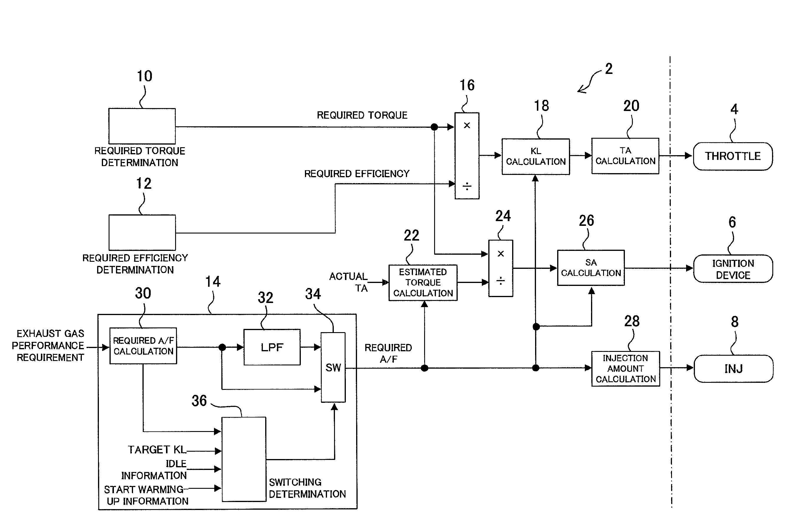
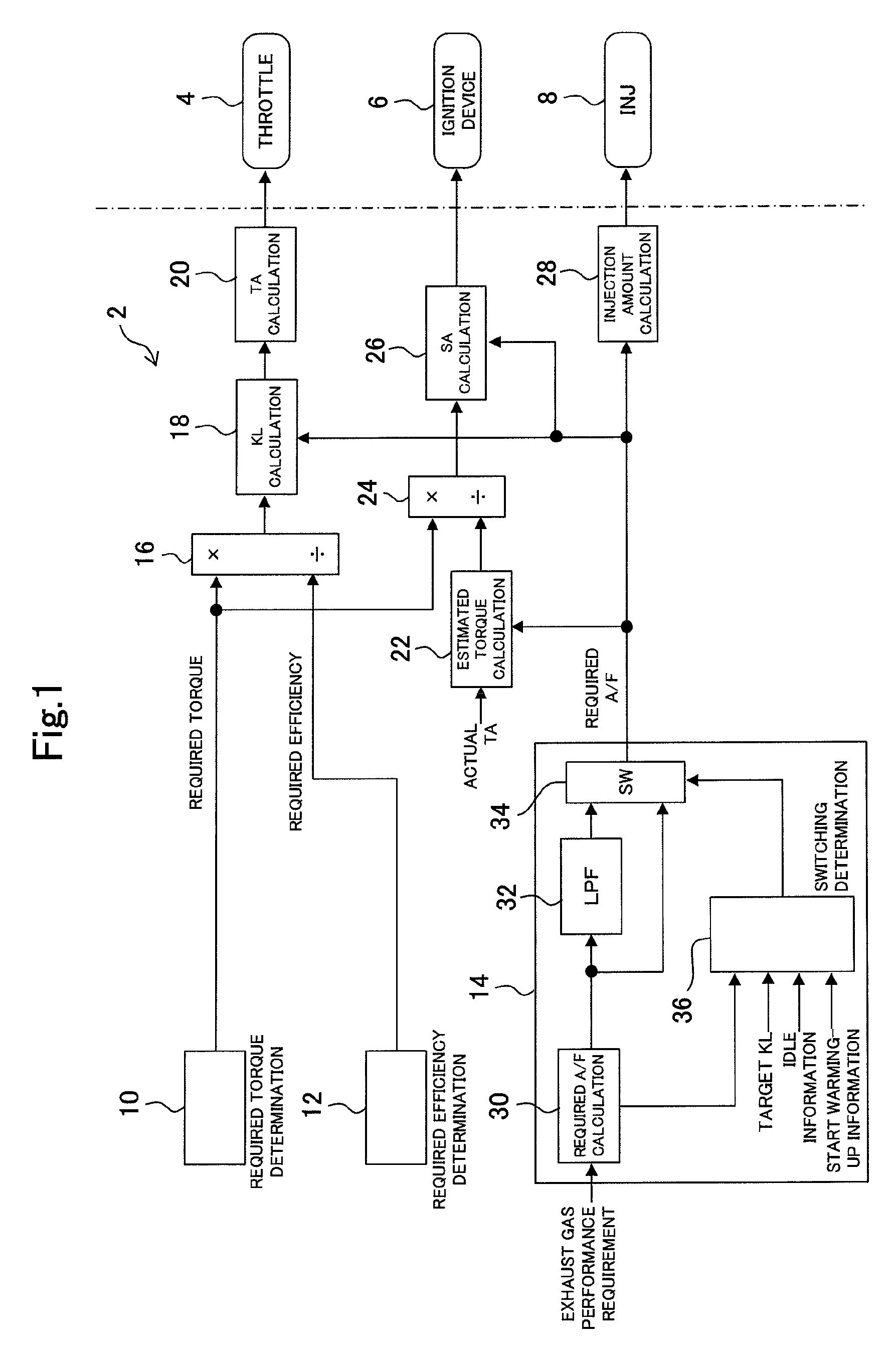
[0044]In embodiment 1 of the present invention, an internal combustion engine (hereinafter, an engine) which is a control object in embodiment 1 of the present invention is a spark ignition type four cycle reciprocating engine. A catalyst device for purifying an exhaust gas is provided in an exhaust passage of the engine. The control device controls the operation of the engine by operating actuators included in the engine. The actuators which can be operated by the control device include an ignition device, a throttle, a fuel injection device, a variable valve timing mechanism, an EGR device and the like. However, in the present embodiment, the control device operates the throttle, the ignition device and the fuel injection device, and the control device controls the operation of the engine by operating these three actuators.

[0045]The control device of the present embodiment uses torque, an ...

embodiment 2

[0069]Embodiment 2 of the present invention will be described with reference to the drawings.

[0070]A difference between the present embodiment and embodiment 1 lies in the determination method of the required air-fuel ratio by the required air-fuel ratio determining unit 14. In more detail, the difference lies in the content of the switching determination of the switch 34 by the switching determining unit 36. Switching determination by the switching determining unit 36 of the present embodiment is performed based on the magnitude of the load of the engine in addition to the change amount of the required air-fuel ratio. This is because the magnitude of the load of the engine is related to the magnitude of the torque variation in the case of the required air-fuel ratio being changed. More specifically, the generation torque of the engine is small at the time of a low load, and the torque variation accompanying the change of the required air-fuel ratio is relatively small. Therefore, i...

embodiment 3

[0073]Embodiment 3 of the present invention will be described with reference to the drawings.

[0074]The present embodiment is common to embodiment 2 in the point that the magnitude of the load of the engine is added to the conditions for reducing the change speed of the required air-fuel ratio. However, the present embodiment is characterized in that the air-fuel ratio change determination value which is the determination reference about the value of the change amount of the required air-fuel ratio is made variable in accordance with the load of the engine.

[0075]FIG. 5 is a diagram expressing the processing performed in the required air-fuel ratio determining unit 14 in the present embodiment in a flowchart. According to the flowchart, the required air-fuel ratio is calculated in the first step S301. Next, the map stored in the switching determining unit 36 is referred to, and the air-fuel ratio change determination value corresponding to the load of the engine is calculated (step S3...


PUM


Abstract

A control device for an internal combustion engine provided by the present invention is a control device which can satisfy both a requirement relating to exhaust gas performance of the internal combustion engine and a requirement relating to operation performance by properly regulating a change speed of a required air-fuel ratio, in the internal combustion engine which uses torque and an air-fuel ratio as control variables. The control device receives the requirement relating to the exhaust gas performance of the internal combustion engine, and calculates an air-fuel ratio which satisfies the requirement as a required air-fuel ratio. When a predetermined reduction condition is not satisfied, an original required air-fuel ratio is directly determined as a final required air-fuel ratio. However, when the reduction condition is satisfied, the change speed is reduced by processing the signal of the original required air-fuel ratio, and determines the required air-fuel ratio with the change speed reduced as the final required air-fuel ration. The reduction condition includes a condition that the change amount of the original required air-fuel ratio, in more detail, a change amount per calculation period is larger than a predetermined air-fuel ratio change determination value.

Description

CROSS REFERENCE TO RELATED APPLICATION[0001]This application is a National Stage of International Application No. PCT / JP2010 / 067882 filed Oct. 12, 2010, the contents of all of which are incorporated herein by reference in their entirety.TECHNICAL FIELD[0002]The present invention relates to a control device for an internal combustion engine, and particularly to a control device for an internal combustion engine with torque and an air-fuel ratio used as control variables.BACKGROUND ART[0003]As one of the methods for controlling internal combustion engines, there is known the method which determines a manipulated variable of each actuator with torque and an air-fuel ratio used as controlled variables. For example, Japanese Patent Laid-Open No. 2010-7489 discloses the method which determines required torque and a required air-fuel ratio for an internal combustion engine, and determines the respective manipulated variables of a throttle, an ignition device, and a fuel injection device in...

Claims


Application Information

Patent Timeline
Patent Type & Authority Patents(United States)
IPC IPC(8): B60T7/12
CPCF02D11/105F02D37/02F02D41/0002F02D41/1475F02D2041/1431F02D2041/1432F02P5/1504Y02T10/42Y02T10/46Y02T10/40
Inventor OKAZAKI, SHUNTAROYOSHIZAKI, SATOSHISHIBAYAMA, MASASHISHOKATSU, KAORUKAWAKAMI, HAJIME
Owner TOYOTA JIDOSHA KK
Learn More