Method to calibrate an optical array, method to display a periodic calibration pattern and a computer program product

a technology of optical array and periodic calibration pattern, applied in image analysis, image enhancement, 2d-image generation, etc., can solve the problems of high-precision calibration plate costs, addition of cost, and previously known calibration methods, and achieve simple geometric shape, simplify the process of locating auxiliary units, and simplify the effect of process

Inactive Publication Date: 2015-08-27
LAVISION
View PDF5 Cites 33 Cited by
  • Summary
  • Abstract
  • Description
  • Claims
  • Application Information

AI Technical Summary

Benefits of technology

[0015]In a preferred embodiment of the invention, the calibration pattern is depicted on the display such that a pattern structure unit is depicted with a reference marking that is optically differentiable, independent of the pattern scale, and in a fixed position relative to the respective edges of the display, and the at least one auxiliary unit is depicted within a pattern structure unit that is fixed relative to the reference marking. This simplifies the process of locating the auxiliary units during automatic calibration. It is not necessary for a corresponding detection algorithm to evaluate the entire calibration pattern being depicted to find an auxiliary unit. Rather, the algorithm can directly evaluate only those pattern structure units in which the auxiliary units are depicted. This is done in that the detection algorithm identifies solely the reference marking and, based on a fixed positional relationship, can directly locate the pattern structure units that are depicted with auxiliary units.
[0016]An especially preferred embodiment provid...

Problems solved by technology

The necessity of having available a plurality of different calibration plate variants for various applications represents an additional expense for the hitherto known calibration methods.
This is disadvantageous especially with regard to the costs associated with these ...

Method used


Image

  • Method to calibrate an optical array, method to display a periodic calibration pattern and a computer program product
  • Method to calibrate an optical array, method to display a periodic calibration pattern and a computer program product
  • Method to calibrate an optical array, method to display a periodic calibration pattern and a computer program product

Examples


Embodiment Construction

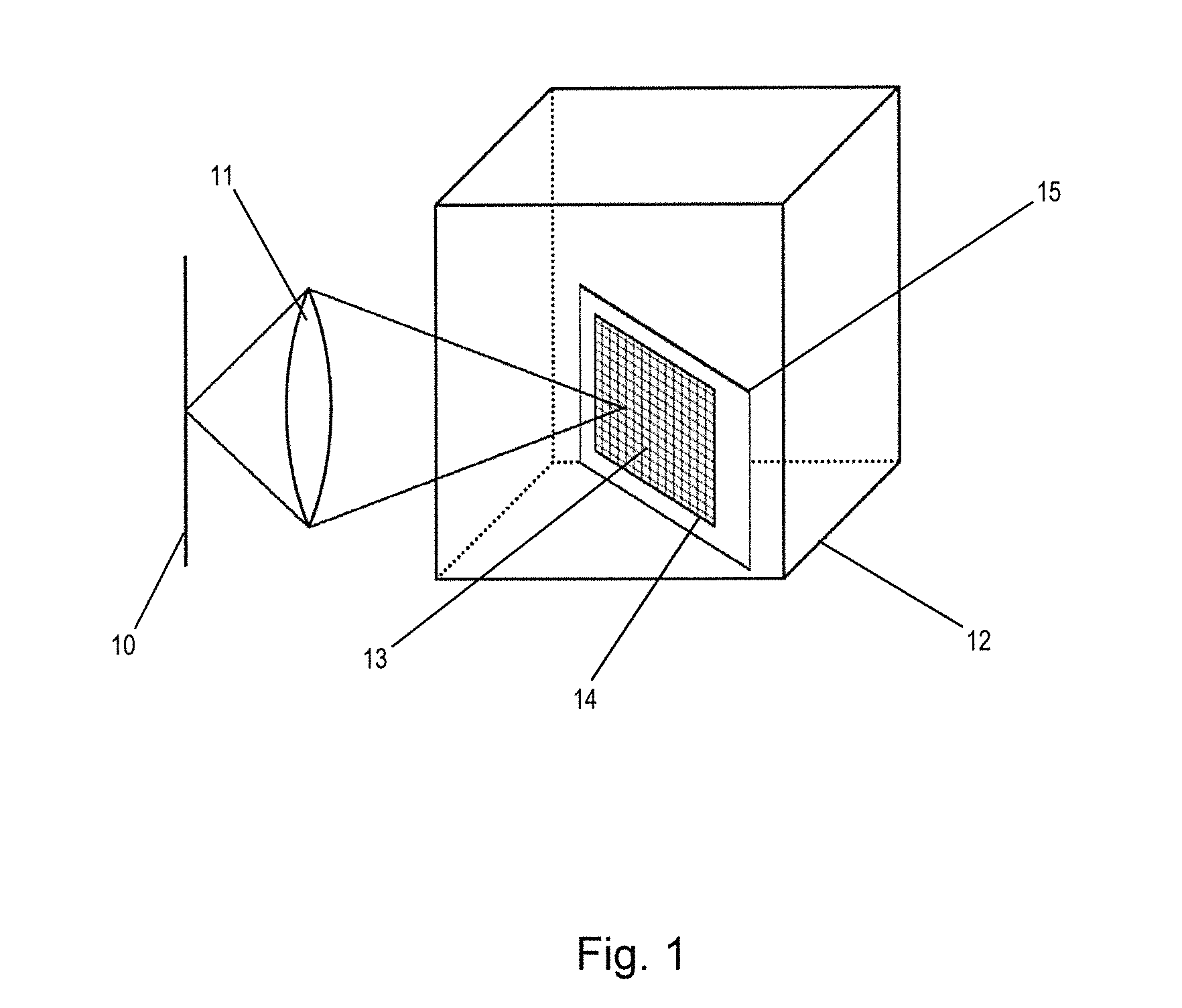
[0026]FIG. 1 shows a representation of the method in accordance with the invention to calibrate an optical array consisting of an image detector 10 and an optical imaging unit 11. The figure additionally shows that the optical imaging unit 11 depicts the points of a calibration pattern 13, located in a measurement volume 12, on the surface of the image detector 10. FIG. 1 also shows that the calibration pattern 13 is depicted on the display 14 of a mobile electronic device 15.

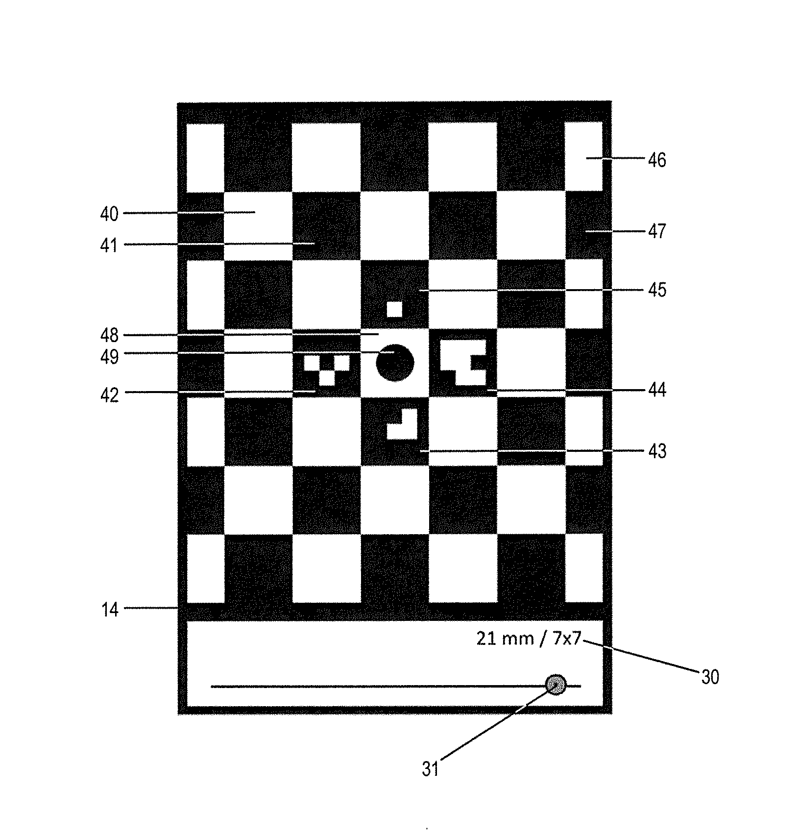
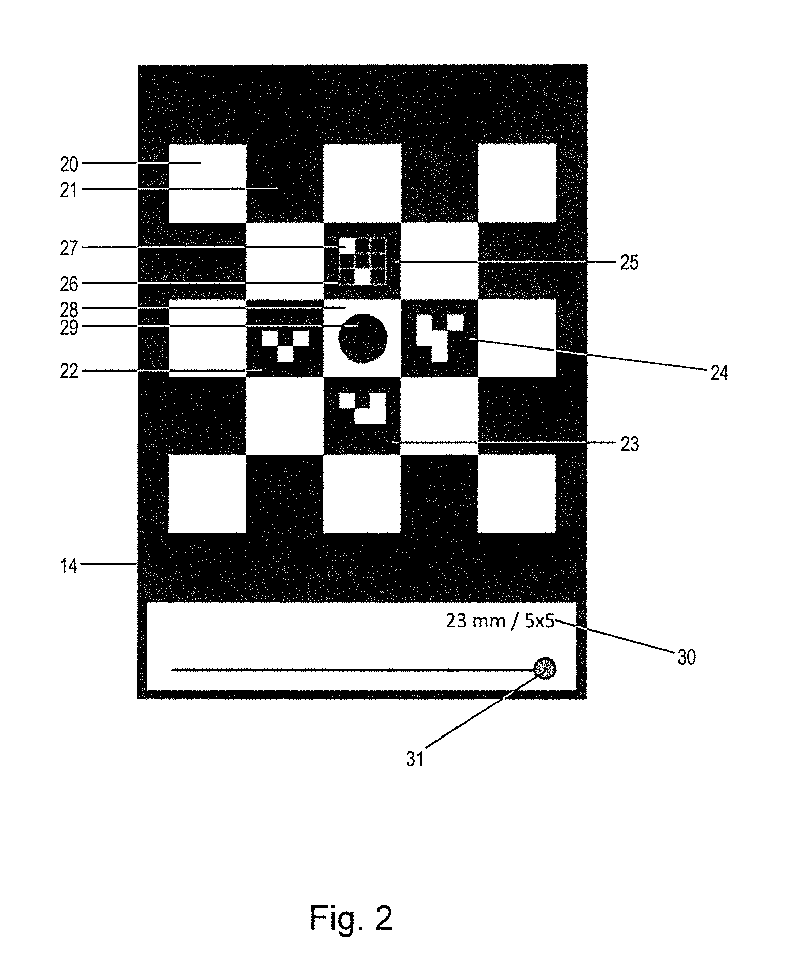
[0027]FIG. 2 is a drawing of an example of a depiction on the display 14 of a mobile electronic device that has been generated by a preferred embodiment of the display method in accordance with the invention. The periodic calibration pattern depicted on the display 14 of a mobile electronic device 15 is composed of pattern structure units 20, 21. The pattern structure units 22, 23, 24 and 25 additionally have an auxiliary unit 26. In FIG. 2, the displayed auxiliary units 26 each consist of nine square auxiliary...


PUM


Abstract

A method is provided to calibrate an optical array consisting of an image detector and an optical imaging unit to depict a measurement volume on the image detector. At least one image of a periodic calibration pattern within a measurement volume is recorded by the optical array and depicted on a display. The calibration pattern has pattern structure units that differ in respect of at least one pattern structure feature, and the pattern scale that is representative of sizes of the pattern structure units is variable. The method correlates positions of the recorded calibration pattern points with image points on which they are displayed. At least one of the pattern structure units is depicted with an optically differentiable auxiliary unit that depends on the current pattern scale, such that the pattern scale can be determined from the depiction features of at least one depicted auxiliary unit.

Description

BACKGROUND[0001]1. Field of the Invention[0002]The invention relates to a method to calibrate an optical array, consisting of an image detector and an optical imaging unit, used to display a measurement volume on the image detector, comprising recording by the optical array of at least one image of a periodic calibration pattern positioned within the measurement volume and depicted on a display of a mobile electronic device, wherein the calibration pattern is composed of pattern structure units differing in respect of at least one pattern structure feature, and the pattern scale that is representative of the sizes of the pattern structure units is variable, and correlation of the positions of the recorded calibration pattern points with the image points on which they are displayed.[0003]The invention further relates to a method to depict a periodic calibration pattern on a display of a mobile electronic device, wherein the calibration pattern is composed of pattern structure units t...

Claims


Application Information

Patent Timeline
IPC IPC(8): G06T7/00G06T11/20
CPCG06T7/0018G06T2207/10004G06T11/20G06T7/0042G06T11/203G06T2207/10024G06T2207/30208G06T7/80
Inventor PFEIFFER, KARSTEN
Owner LAVISION
Why Eureka
Try Eureka