Liquid-crystal display device and drive method thereof

a technology of display device and liquid crystal, which is applied in the direction of electric digital data processing, instruments, computing, etc., can solve the problems that the liquid crystal display device mounted as a display device in such electronic equipment has been required to consume low electric power, and achieve the effect of reducing the power consumption of the liquid crystal display device, and constant pause period

Active Publication Date: 2015-08-27
SHARP KK
View PDF9 Cites 26 Cited by
  • Summary
  • Abstract
  • Description
  • Claims
  • Application Information

AI Technical Summary

Benefits of technology

[0035]According to the first aspect of the present invention, when image data received from the outside is updated, a refresh is performed once by use of the updated image data, and next, a refresh pauses just in a pause period that is decided in accordance with a refresh rate of the image data. Then, after the end of the pause period, a refresh is performed at least once or more by use of the same image data as the updated image data. Hence it is possible to perform a plurality of refreshes in a short period after receiving the updated image data, so as to make the liquid crystal molecules oriented in the direction corresponding to the applied voltage in a short time. Hence it is possible to make an afterimage during the pause drive, which is caused by anisotropy of a liquid crystal dielectric constant, visually unrecognizable while suppressing the power consumption of the liquid crystal display device.
[0036]According to the second aspect of the present invention, since a refresh can be performed by use of the updated image data three times in total, it is possible to make the liquid crystal molecules oriented in the direction corresponding to the applied voltage. Hence it is possible to make an afterimage, which is caused by anisotropy of a liquid crystal dielectric constant, visually unrecognizable.
[0037]According to the third aspect of the present invention, since twice of refreshes, which are performed after the end of the pause period, are consecutively performed, it is possible to finish in a short time a total of three times of refreshes that are performed by use of the updated image data. Hence it is possible to make an afterimage during the pause drive, which is caused by anisotropy of a liquid crystal dielectric constant, visually unrecognizable.
[0038]According to the fourth aspect of the present invention, twice of refreshes that are performed after a lapse of the pause period are performed with a period for making a refresh pause therebetween. Thereby, when the refresh rate of the image data is 10 Hz, a refresh is performed once after the lapse of the pause period, and hence it is possible to reduce the power consumption of the liquid crystal display device.
[0039]According to the fifth aspect of the present invention, the refresh rate during the pause drive is irregularly switched, and a length of the pause period is changed accordingly. As thus described, by resetting the length of the pause period, it is possible to reliably make an afterimage during the pause drive visually unrecognizable regardless of the refresh rate.
[0040]According to the sixth aspect of the present invention, even when the refresh rate during the pause drive is irregularly switched, the length of the pause period is constant. In this case, since only one register for storing the length of the pause period may be provided, it is possible to reduce manufacturing cost of the liquid crystal display device.

Problems solved by technology

A liquid crystal display device mounted as a display device in such electronic equipment has been required to consume low electric power.

Method used


Image

  • Liquid-crystal display device and drive method thereof
  • Liquid-crystal display device and drive method thereof
  • Liquid-crystal display device and drive method thereof

Examples


first embodiment

2. First Embodiment

2.1 Configuration and Operation Summary of Liquid Crystal Display Device

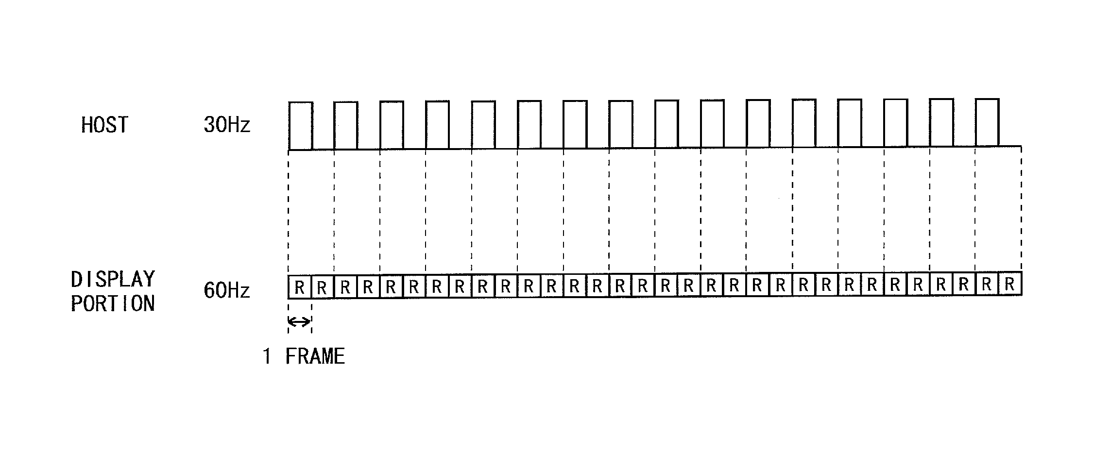
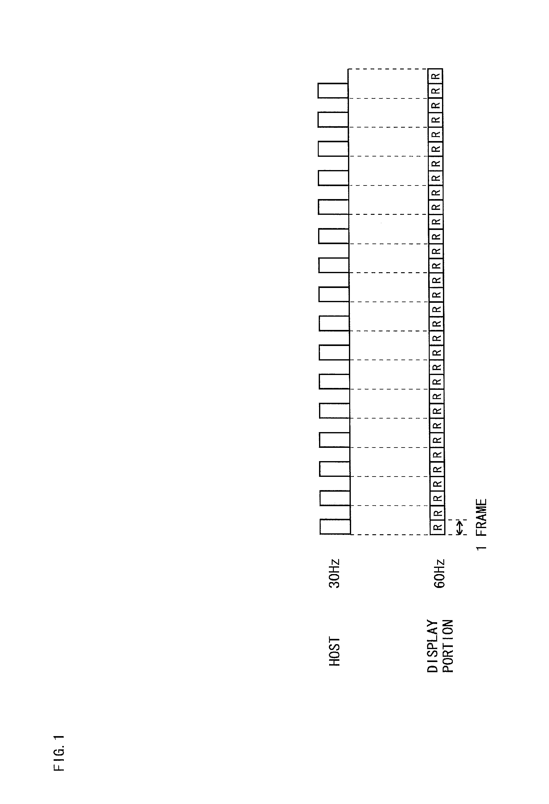
[0080]FIG. 4 is a block diagram showing a configuration of a liquid crystal display device 2 according to a first embodiment of the present invention. As shown in FIG. 4, the liquid crystal display device 2 is provided with a liquid crystal display panel 10 and a backlight unit 30. The liquid crystal display panel 10 is provided with an FPC (Flexible Printed Circuit) 20 for connection with the outside. Further, a display portion 100, a display control circuit 200, a signal line drive circuit 300 and a scanning line drive circuit 400 are provided on the liquid crystal display panel 10. It is to be noted that both or either one of the signal line drive circuit 300 and the scanning line drive circuit 400 may be provided in the display control circuit 200. Further, both or either one of the signal line drive circuit 300 and the scanning line drive circuit 400 may be formed integrally with the disp...

second embodiment

3. Second Embodiment

[0120]FIG. 11 is a diagram for explaining an operation, in the pause drive, of the liquid crystal display device 2 according to a second embodiment of the present invention. It is to be noted that, since the present embodiment is similar to the above first embodiment except for the operation in the pause drive, there will be omitted a block diagram showing the configuration of the liquid crystal display device 2 and the configuration of the display control circuit 200 included in the liquid crystal display device 2, and descriptions thereof.

3.1 Operation in Pause Drive

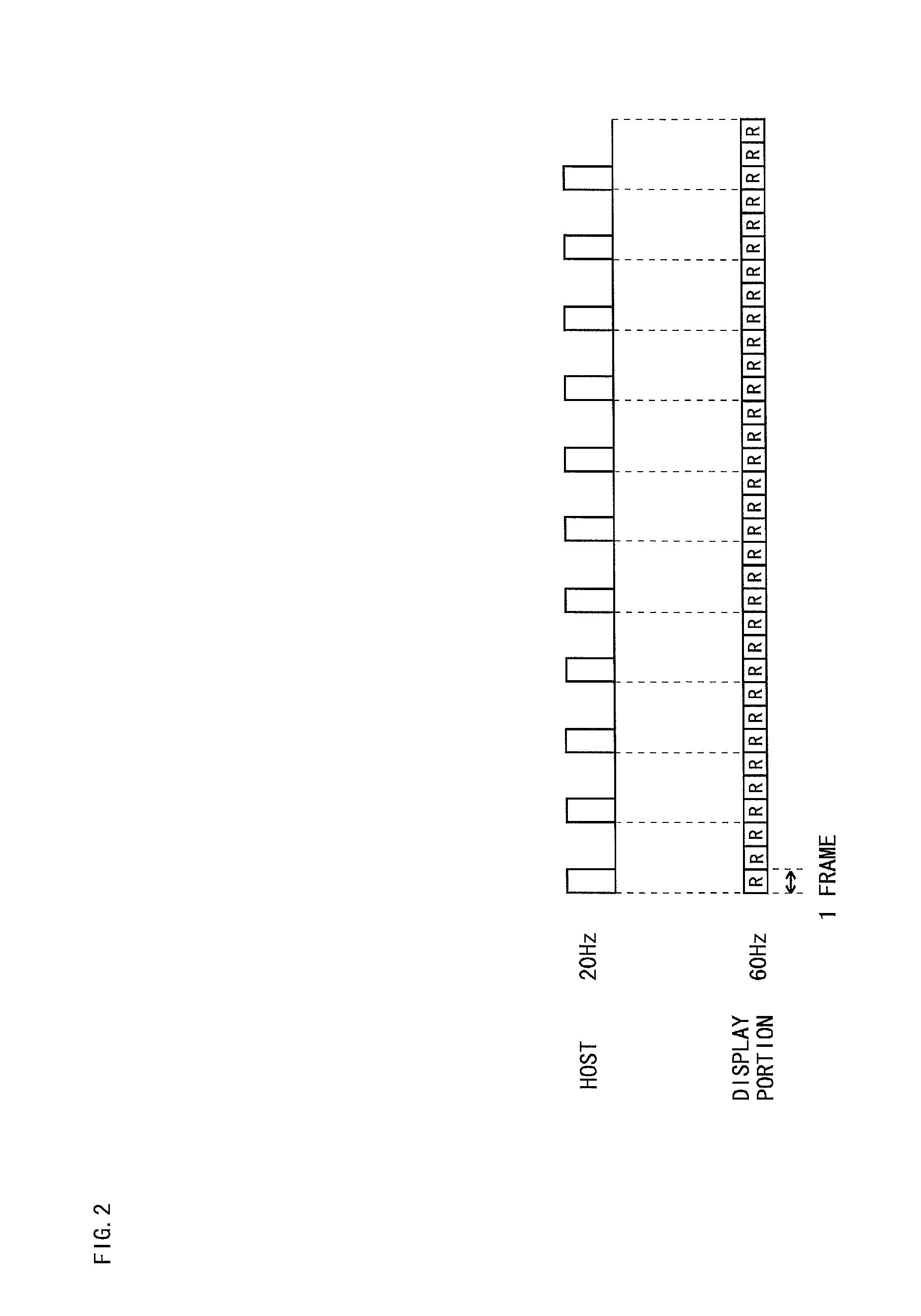
[0121]In the above first embodiment, updated image data is transmitted from the host 1 at a constant frame rate (e.g., 5 Hz). However, the refresh rate of the image data may be switched after the start of the pause drive. In the present embodiment, when this refresh rate is switched is assumed to be previously known.

[0122]As shown in FIG. 11, for example, it is assumed to be previously known that th...

third embodiment

4. Third Embodiment

[0135]FIG. 14 is a diagram for explaining an operation, in the pause drive, of the liquid crystal display device 2 according to a third embodiment of the present invention. It is to be noted that, since the present embodiment is similar to the above first embodiment except for the operation in the pause drive, there will be omitted a block diagram showing the configuration of the liquid crystal display device 2 and the configuration of the display control circuit 200 included in the liquid crystal display device 2, and descriptions thereof.

4.1 Operation in Pause Drive

[0136]Throughout the pause drive period, when a balance between positive polarity and negative polarity of the applied voltage of the liquid crystal capacitance Ccl is not considered, the time when a voltage in a specific direction is applied to the liquid crystal layer becomes long, causing the deterioration in liquid crystal layer to tend to be accelerated. Accordingly, in the present embodiment, an...


PUM


Abstract

Provided are a liquid crystal display device and a drive method thereof, capable of promptly making an afterimage, which is visually recognized during pause drive, visually unrecognizable while suppressing power consumption. When updated image data is transmitted, a first refresh is performed by used of this image data, and a refresh pauses based on Ref_int just in the next two-frame period. Then, the second and third refreshes are consecutively performed, and a refresh pause is repeated until the next updated image data is transmitted. In this case, since a refresh can be performed three times in a short period after reception of the updated image data, it is possible to make liquid crystal molecules oriented in a direction corresponding to an applied voltage in a short time and make an afterimage visually unrecognizable.

Description

TECHNICAL FIELD[0001]The present invention relates to a liquid crystal display device and a drive method thereof, and specifically relates to a liquid crystal display device that displays an image by pause drive, and a drive method thereof.BACKGROUND ART[0002]In recent years, small-sized lightweight electronic equipment has been under active development. A liquid crystal display device mounted as a display device in such electronic equipment has been required to consume low electric power. As one of drive methods for reducing power consumption of the liquid crystal display device, there is a drive method called “pause drive” in which a scanning period for scanning scanning lines to refresh a screen is provided and then a pause period (non-refresh period) for bringing all scanning lines into a non-scanning state to make a refresh pause is provided. In this drive method, a controlling signal or the like is not given to a scanning line drive circuit and / or a signal line drive circuit i...

Claims


Application Information

Patent Timeline
Patent Type & Authority Applications(United States)
IPC IPC(8): G09G5/18G09G3/36
CPCG09G5/18G09G2330/021G09G3/3696G09G3/2096G09G3/3611G09G3/3614G09G3/3648G09G2310/0278G09G2320/0252G09G2340/0435G09G2360/18G09G2370/022
Inventor SONE, TAKUYATANAKA, NORIYUKI
Owner SHARP KK
Why Eureka
Try Eureka