Eureka AIR delivers breakthrough ideas for toughest innovation challenges, trusted by R&D personnel around the world.

Methods of patterning line-type features using a multiple patterning process that enables the use of tighter contact enclosure spacing rules

a patterning process and patterning technology, applied in the field of sophisticated semiconductor devices, can solve the problems of reducing device dimensions and pitches, negative impact on chip shrinkage, photolithography tools, etc., and achieve the effect of tighter contact enclosure spacing rules

Active Publication Date: 2015-08-27
GLOBALFOUNDRIES US INC
View PDF1 Cites 24 Cited by
  • Summary
  • Abstract
  • Description
  • Claims
  • Application Information

AI Technical Summary

Benefits of technology

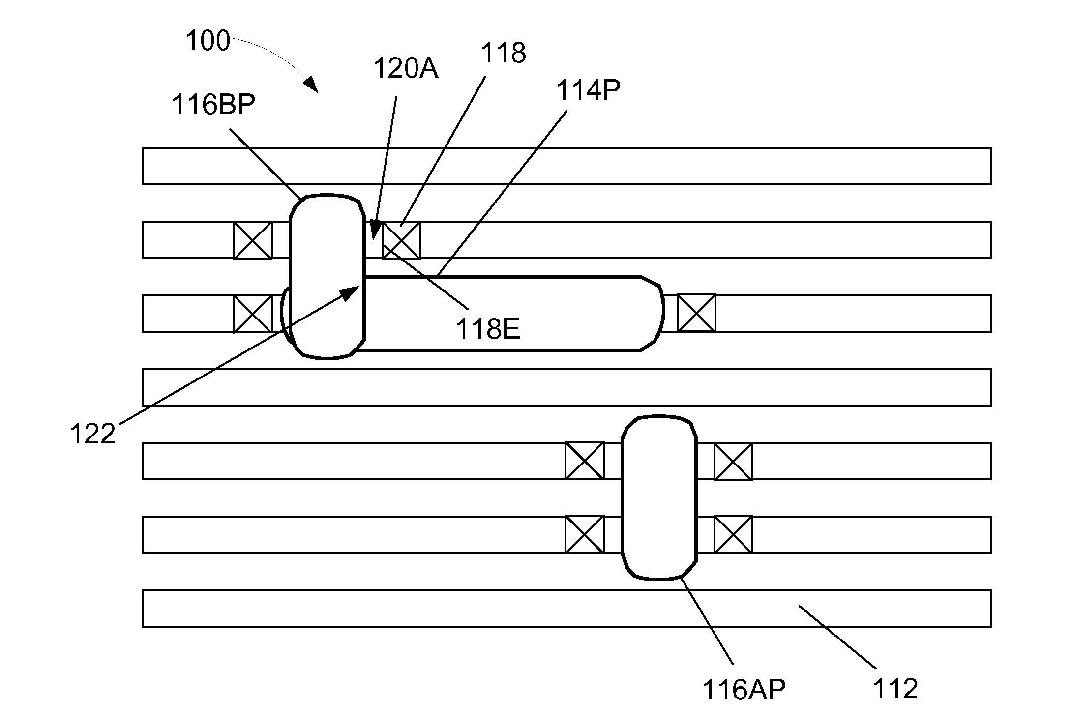
The present invention provides methods for patterning line-type features on a semiconductor substrate using a stitched, multiple patterned cut mask. These methods involve identifying an overall target cut mask, decomposing it into sub-target patterns, and using them to cut the line-type features. The methods also involve identifying a contact that is to be formed so as to conductively contact the cut line-type feature and generating mask data based upon a spacing rule for the contact. The technical effects of the invention include improved patterning accuracy and efficiency, as well as reduced costs and improved reliability.

Problems solved by technology

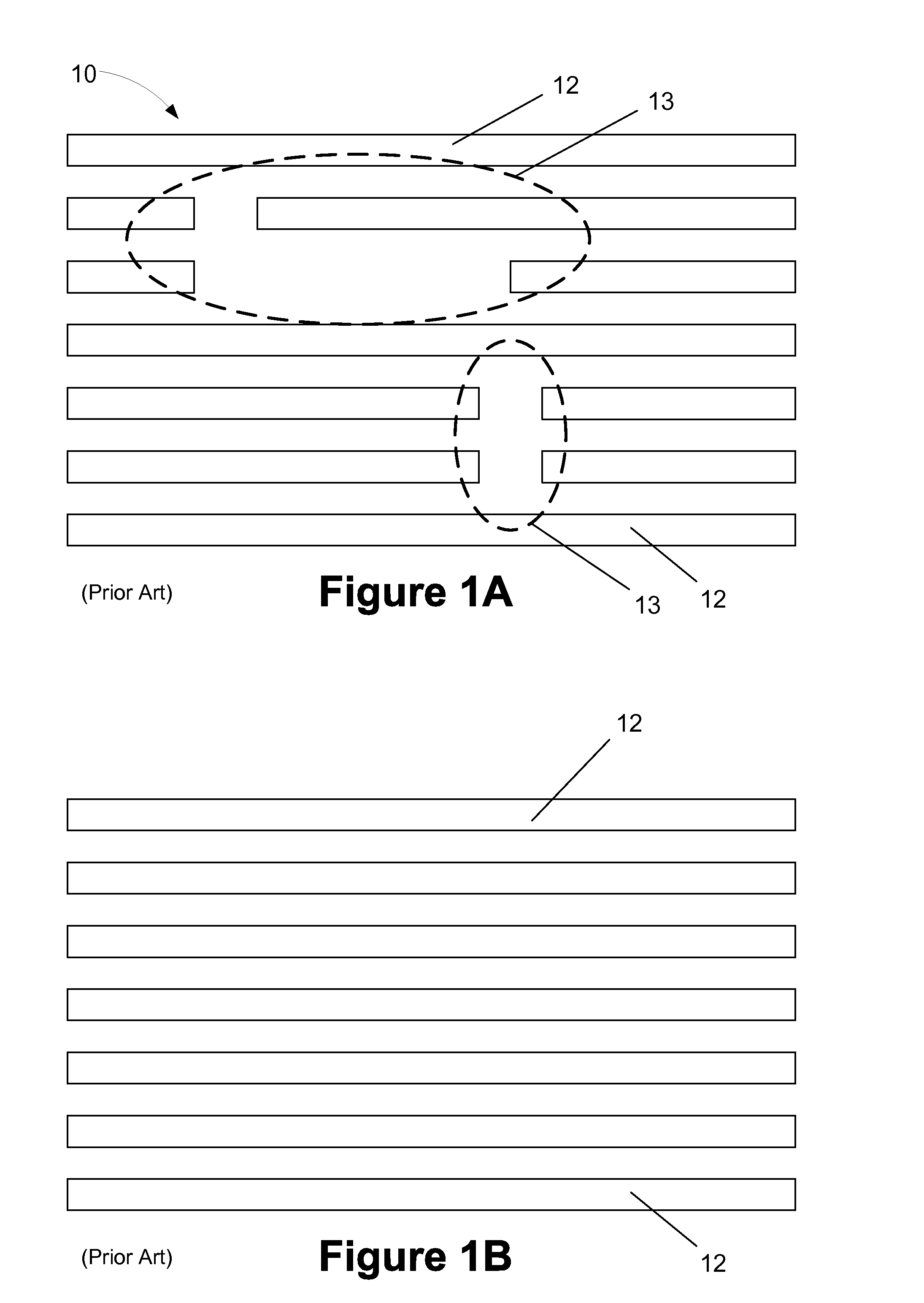
However, in recent years, device dimensions and pitches have been reduced to the point where existing photolithography tools, e.g., 193 nm wavelength immersion photolithography tools, cannot form a single patterned mask layer with all of the features of the overall target pattern.
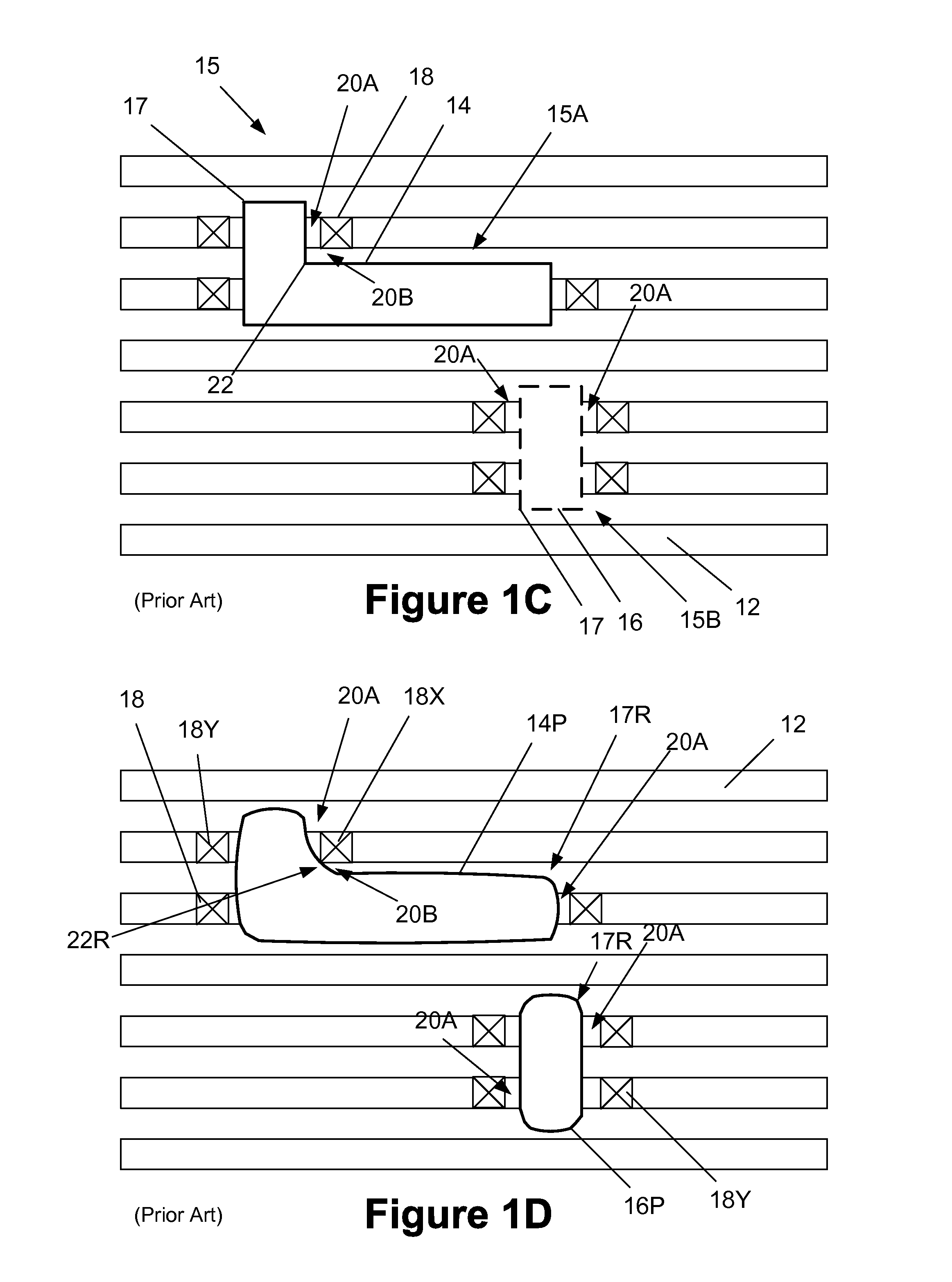
One common issue that occurs when trying to use a cut mask is that the inner corner rounding of non-rectangular features in a cut mask necessitate a large contact enclosure distance for the associated contact, which has negative impact on chip shrinkage.
However, corner rounding of the inner corner 22 of the non-rectangular opening 14 can cause several problems.
As a result, there may be insufficient landing area for the contact 18X when it is formed, thereby making accurate alignment more difficult (considering necessary processing margins) and perhaps resulting in a contact structure that operates under conditions not anticipated by the design process.
For example, if the contact area between the contact 18X and the underlying line 12 is less than anticipated by the design process, there may be a corresponding increase in electrical resistance, which may degrade device performance or may even result in a non-functioning circuit.
One way to resolve the negative aspects of such corner rounding would be to increase the spacing between the end of a cut line 12 and the contact 18X, but such a corrective action would result in undesirable consumption of extremely valuable plot space on the substrate.

Method used


Image

  • Methods of patterning line-type features using a multiple patterning process that enables the use of tighter contact enclosure spacing rules
  • Methods of patterning line-type features using a multiple patterning process that enables the use of tighter contact enclosure spacing rules
  • Methods of patterning line-type features using a multiple patterning process that enables the use of tighter contact enclosure spacing rules

Examples


Embodiment Construction

[0022]Various illustrative embodiments of the invention are described below. In the interest of clarity, not all features of an actual implementation are described in this specification. It will of course be appreciated that in the development of any such actual embodiment, numerous implementation-specific decisions must be made to achieve the developers' specific goals, such as compliance with system-related and business-related constraints, which will vary from one implementation to another. Moreover, it will be appreciated that such a development effort might be complex and time-consuming, but would nevertheless be a routine undertaking for those of ordinary skill in the art having the benefit of this disclosure.

[0023]The present subject matter will now be described with reference to the attached figures. Various structures, systems and devices are schematically depicted in the drawings for purposes of explanation only and so as to not obscure the present disclosure with details ...


PUM


Abstract

A method involving identifying a pattern for an overall target cut mask to be used in patterning line-type features that includes a target non-rectangular opening feature having an inner, concave corner, decomposing the overall target cut mask pattern into first and second sub-target patterns, wherein the first sub-target pattern comprises a first rectangular-shaped opening feature corresponding to a first portion, but not all, of the target non-rectangular opening feature and the second sub-target pattern comprises a second rectangular-shaped opening feature corresponding to a second portion, but not all, of the target non-rectangular opening feature, the first and second openings overlapping adjacent the inner, concave corner, and generating first and second sets of mask data corresponding to the first and second sub-target patterns, wherein at least one of the first and second sets of mask data is generated based upon an identified contact-to-end-of-cut-line spacing rule.

Description

BACKGROUND OF THE INVENTION[0001]1. Field of the Invention[0002]Generally, the present disclosure relates to the manufacture of sophisticated semiconductor devices, and, more specifically, to various methods of patterning line-type features using a stitched, multiple patterned cut mask that enables the use of tighter contact enclosure spacing rules.[0003]2. Description of the Related Art[0004]Photolithography is one of the basic processes used in manufacturing integrated circuit products. At a very high level, photolithography involves: (1) forming a layer of light or radiation-sensitive material, such as photoresist, above a layer of material or a substrate; (2) selectively exposing the radiation-sensitive material to a light generated by a light source (such as a DUV or EUV source) to transfer a pattern defined by a mask or reticle (interchangeable terms as used herein) to the radiation-sensitive material; and (3) developing the exposed layer of radiation-sensitive material to def...

Claims


Application Information

Patent Timeline
Patent Type & Authority Applications(United States)
IPC IPC(8): H01L21/308H01L21/768H01L21/306G06F17/50
CPCH01L21/3088G06F17/5068H01L21/3081H01L21/76877H01L21/30604H01L21/76816H01L21/0273H01L21/0278H01L21/0274H01L21/32139G03F1/70G03F7/0002G06F30/39
Inventor YUAN, LEIKYE, JONGWOOKLEVINSON, HARRY J.
Owner GLOBALFOUNDRIES US INC
Why Eureka
Eureka Blog
Learn More