Corrodible Wellbore Plugs and Systems and Methods Including the Same

US20150247376A1Active Publication Date: 2015-09-03EXXONMOBIL UPSTREAM RES CO

Image

  • Corrodible Wellbore Plugs and Systems and Methods Including the Same
  • Corrodible Wellbore Plugs and Systems and Methods Including the Same
  • Corrodible Wellbore Plugs and Systems and Methods Including the Same

Examples


Embodiment Construction

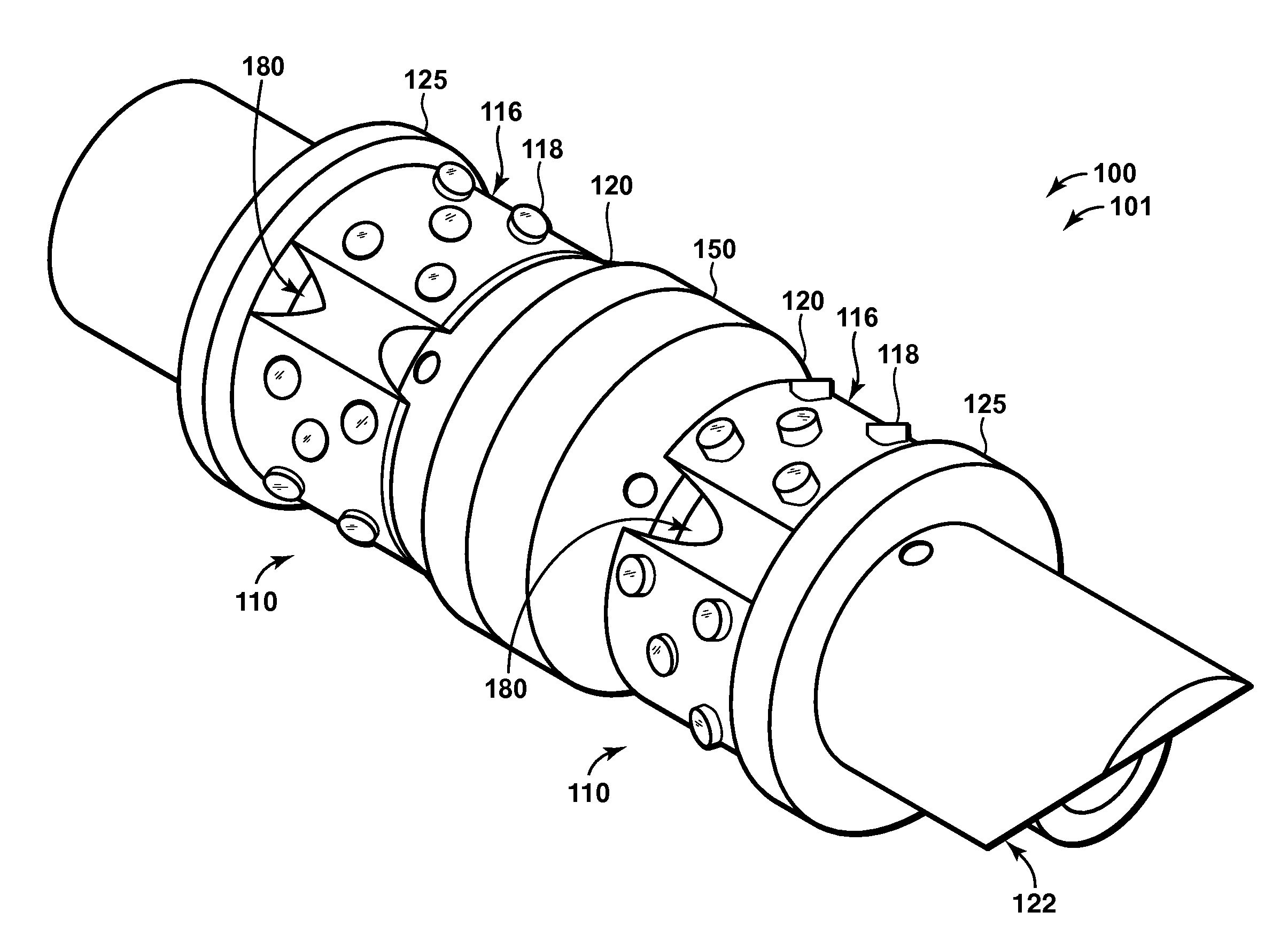
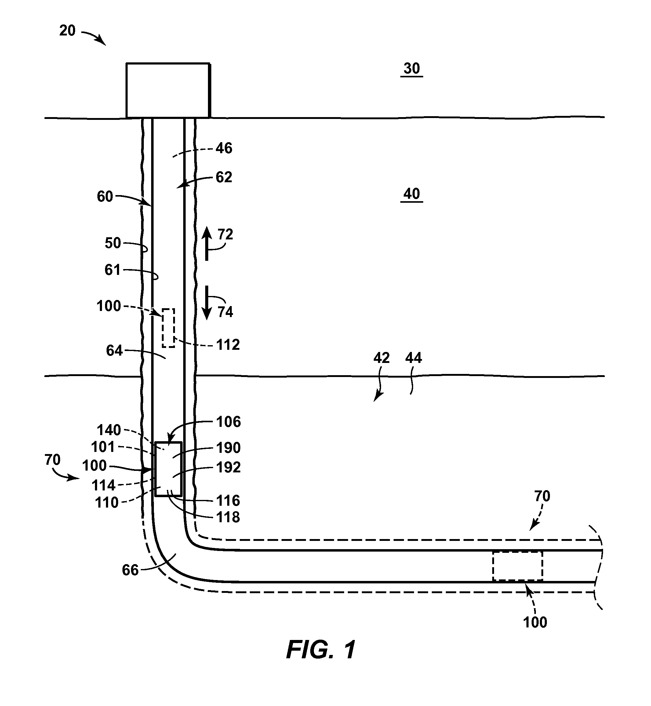
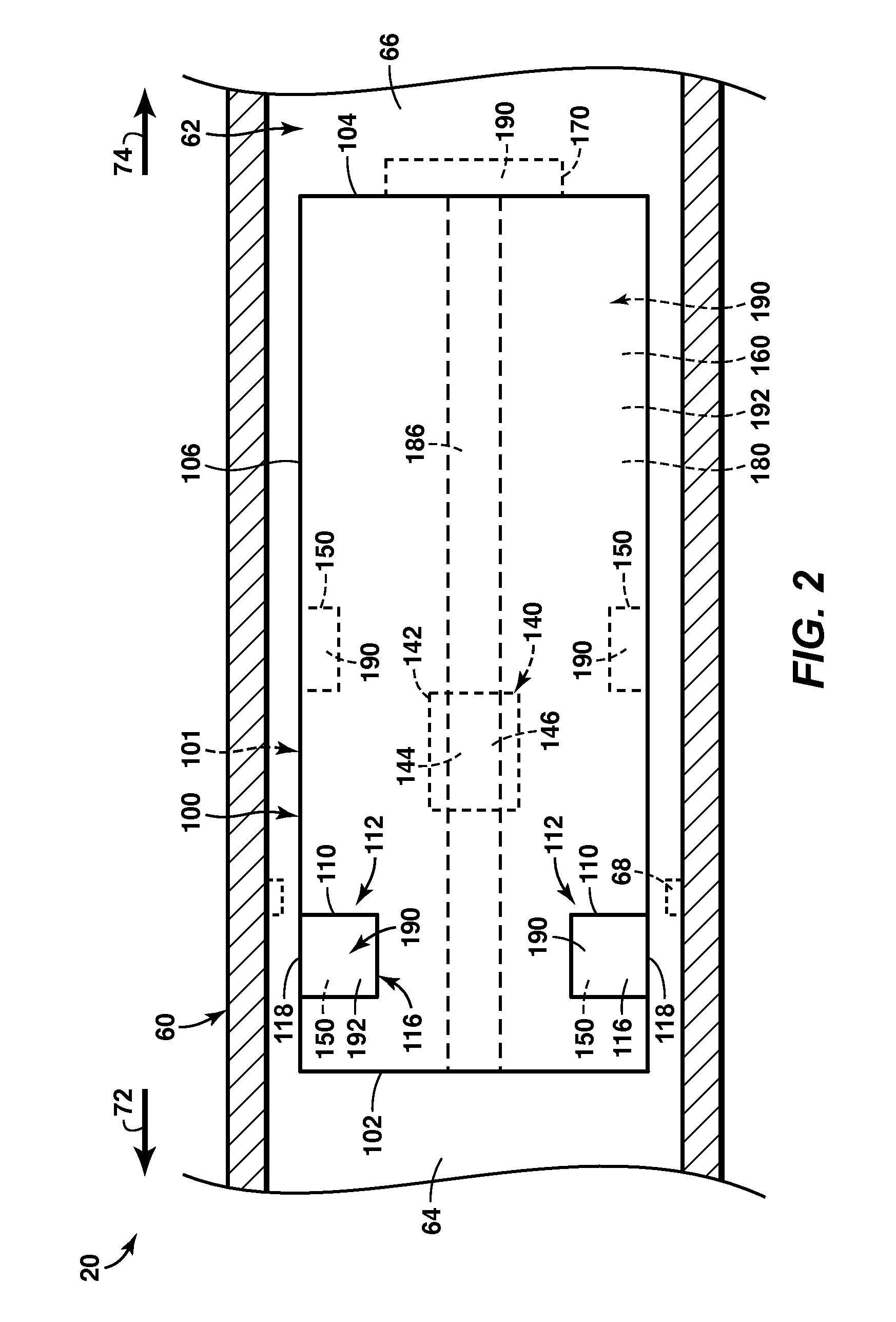
[0032]FIGS. 1-13 provide illustrative, non-exclusive examples of corrodible wellbore plugs 100 according to the present disclosure, components of corrodible wellbore plugs 100, hydrocarbon wells 20 that include and / or utilize corrodible wellbore plugs 100, and / or methods that may include and / or utilize corrodible wellbore plugs 100. Elements that serve a similar, or at least substantially similar, purpose are labeled with like numbers in each of FIGS. 1-13, and these elements may not be discussed in detail herein with reference to each of FIGS. 1-13. Similarly, all elements may not be labeled in each of FIGS. 1-13, but reference numerals associated therewith may be utilized herein for consistency. Elements, components, and / or features that are discussed herein with reference to one or more of FIGS. 1-13 may be included in and / or utilized with any of FIGS. 1-13 without departing from the scope of the present disclosure.

[0033]In general, elements that are likely to be included are ill...


PUM


Abstract

Corrodible wellbore plugs, systems and methods are disclosed herein. The methods include flowing a corrodible wellbore plug that is at least partially formed from a corrodible metal to a downhole location within a wellbore conduit and retaining the corrodible wellbore plug at the downhole location by operatively engaging an engagement structure with a wellbore tubular that defines the wellbore conduit. The methods include pressurizing a portion of the wellbore conduit uphole from the corrodible wellbore plug and flowing a corrosive reservoir fluid from the subterranean formation into contact with the corrodible metal to release the corrodible wellbore plug from the downhole location. The methods also may include removing the wellbore plug without utilizing a drill-out process. The systems include a corrodible wellbore plug that includes a plug body and a retention mechanism, which includes a slip ring formed from the corrodible metal and that includes the engagement structure.

Description

CROSS-REFERENCE TO RELATED APPLICATION[0001]This application claims priority to U.S. Provisional Patent Application No. 61 / 946,590, filed Feb. 28, 2014, entitled CORRODIBLE ALUMINUM TOOLS AND PLUGS, and U.S. Provisional Patent Application No. 62 / 023,679, filed Jul. 11, 2014, entitled CORRODIBLE WELLBORE PLUGS AND SYSTEMS AND METHODS INCLUDING THE SAME, both of which are incorporated in their entirety herein.FIELD OF THE DISCLOSURE[0002]The present disclosure is directed to corrodible wellbore plugs and to methods of utilizing corrodible wellbore plugs.BACKGROUND OF THE DISCLOSURE[0003]A variety of wellbore plugs may be utilized to restrict and / or block fluid flow within a hydrocarbon well that includes a wellbore conduit that extends within a subterranean formation. Often, a wellbore plug is utilized for a period of time and subsequently is removed from the wellbore conduit. As an example, a plug may be utilized to fluidly isolate an uphole portion of the wellbore conduit from a dow...

Claims


Application Information

Patent Timeline
03 Sep 2015
Publication
US20150247376A1
IPC
E21B33/129; E21B23/01; E21B36/00; E21B43/114
CPC
E21B33/1292; E21B43/114; E21B2034/002; E21B36/00; E21B23/01; E21B33/12; E21B33/1208; E21B33/1293
Inventors
TOLMAN, RANDY C.; HALL, TIMOTHY J.