Urea water supply system

a technology of urea water supply and water supply system, which is applied in the direction of engines, mechanical equipment, machines/engines, etc., can solve the problems of adverse effects on the components involved in the supply of urea water, and achieve the effect of suppressing the occurren

Active Publication Date: 2017-01-24
TOYOTA JIDOSHA KK
View PDF17 Cites 3 Cited by
  • Summary
  • Abstract
  • Description
  • Claims
  • Application Information

AI Technical Summary

Benefits of technology

[0009]A proposed technique provides two NOx catalysts placed in the exhaust passage for the purpose of removing NOx in the exhaust emission discharged from the internal combustion engine. The two NOx catalysts may be provided for various reasons, for example, providing two exhaust passages extended from an internal combustion engine or enhancing the efficiency of removal of NOx as much as possible. In any reason, in the technique of providing two NOx catalysts in the exhaust passage, one applicable configuration may place two supply valves corresponding to the two NOx catalysts for supplying ammonia efficiently to the respective NOx catalysts and supply the amount of urea water required for each NOx catalyst from the supply valve to the exhaust emission. In the above configuration of placing the two supply valves for supply of urea water, a pump used to pressure-feed the urea water to the respective supply valves may be shared by the respective supply valves, in order to reduce an increase in total number of components. The configuration of supplying urea water from a common pump to a plurality of supply valves is called “pump share-type” in the description below.
[0010]The urea included in urea water is the precursor of ammonia. When urea water is not supplied from the supply valve to the exhaust emission but remains in the supply valve or in a supply path connecting with the supply valve, ammonia may be produced from the remaining urea water by, for example, heat energy from the exhaust passage and accelerate corrosion of the supply valve or the supply path. The urea water filled in the supply valve and the supply path is thus required to be sucked back to a tank, when there is no need to continue supplying the urea water to the exhaust emission for the purpose of reduction of NOx. When supply of urea water to the exhaust emission is needed again, the supply valve and the supply path are filled with urea water again to prepare for resuming supply of urea water to the exhaust emission.

Problems solved by technology

This may adversely affect components involved in supply of urea water, for example, the supply valve and a pump for pressure-feeding urea water.
More specifically, Patent Literature 1 has noted that urea depositing by vaporization of water after a stop of operation of the pump is likely to enter the clearance between components of the pump and cause a trouble and provides a configuration of making a continuous flow of urea water in the pump even after a stop of operation of the pump, in order to suppress deposition of urea.

Method used


Image

  • Urea water supply system
  • Urea water supply system
  • Urea water supply system

Examples


first embodiment

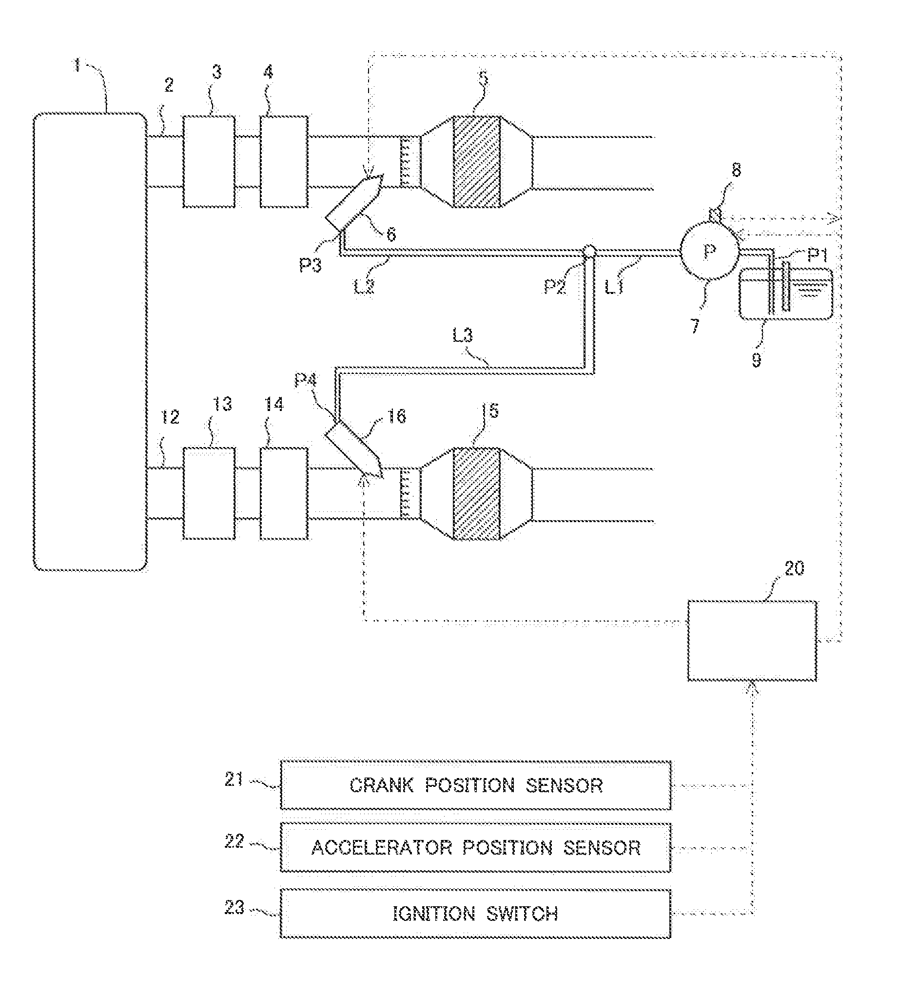
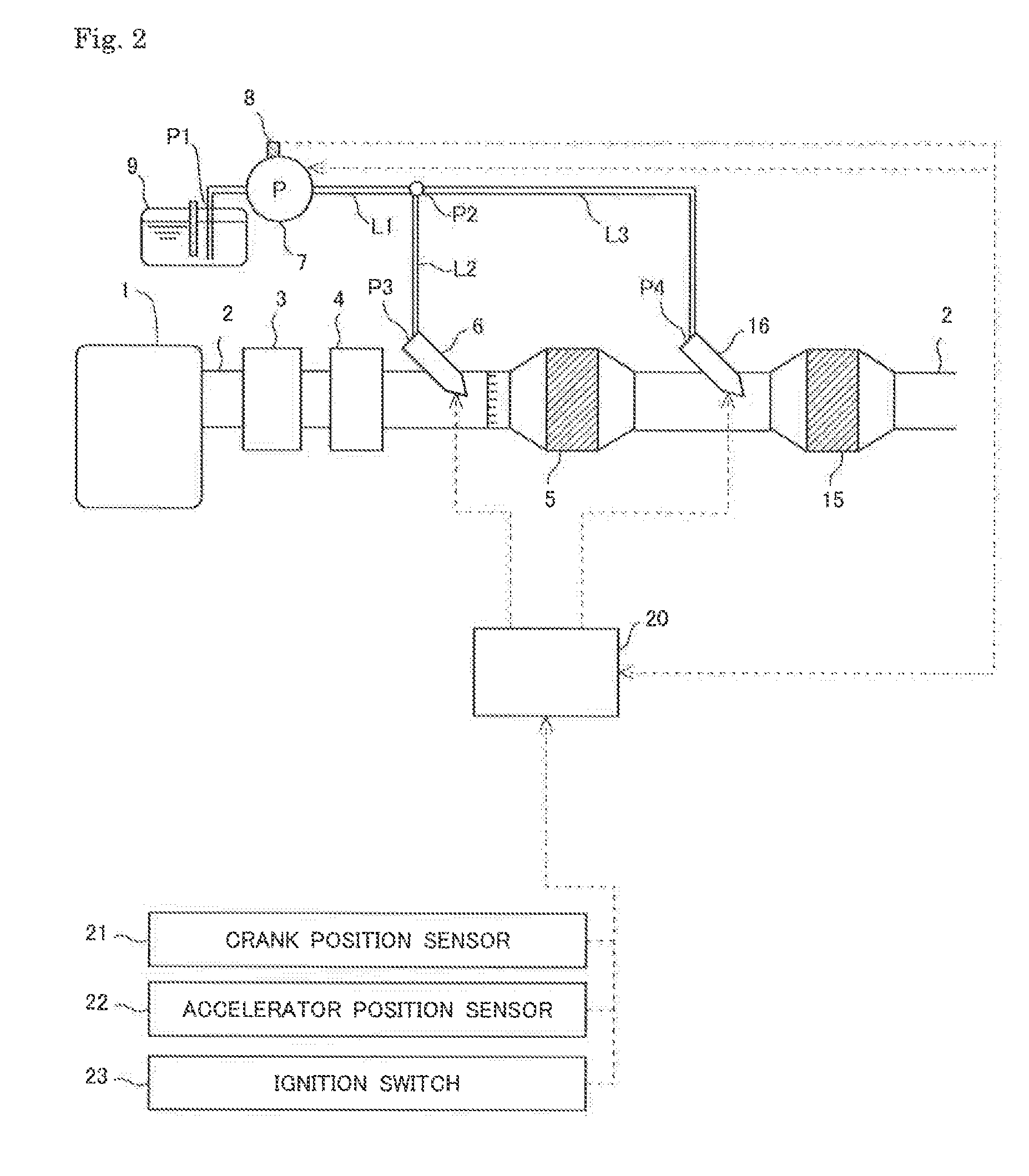
[0039]The following describes the schematic configurations of a urea water supply system (hereinafter may simply be referred to as “system”) and an exhaust emission control device of an internal combustion engine which the system is applied to, with reference to FIGS. 1 and 2. An internal combustion engine 1 shown in FIG. 1 is a diesel engine for driving a vehicle. The internal combustion engine of the invention is, however, not limited to the diesel engine but may be a gasoline engine or the like. The urea water supply system of the invention is configured to supply urea water to supply valves that are arranged to supply ammonium as a reducing agent to two NOx catalysts provided in an exhaust passage of the internal combustion engine 1. Exhaust emission control devices of FIGS. 1 and 2 are illustrated as examples of the exhaust emission control device of the internal combustion engine which the system is applied to and are not at all intended to limit the application of the inventi...

second embodiment

[0070]The following describes a second embodiment with regard to open-close control of the respective supply valves in filling control of urea water with reference to FIG. 6. FIG. 7 shows a time chart showing (a) variation in setting of the filling ready flag, (b) variation in pump rotation signal, (c) variation in open-close signal of the first supply valve 6, (d) variation in open-close signal of the second supply valve 16, (e) variation in amount of urea water in the supply path L2, (f) variation in amount of urea water in the supply path L3 and (g) variation in internal pressure of the supply path L1 with respect to the open-close control of the respective supply valves in the filling control shown in FIG. 6. The filling control shown in FIG. 6 is performed by the ECU 20 like the filling control shown in FIG. 3. The like steps in the filling control of FIG. 6 that are substantially similar to the steps in the filling control of FIG. 3 are expressed by the like step numbers and a...


PUM


Abstract

An object is to suppress the occurrence of a failure in supply of urea water as much as possible in filling control of urea water in a pump share-type urea water supply system with two supply valves. In the pump share-type urea water supply system with a first supply valve and a second supply valve, a urea water tank is connected with the respective supply valves by a urea water supply path. The urea water supply path includes a first supply path for the first supply valve and a second supply path for the second supply valve. The second supply path has a larger capacity than the capacity of the first supply path by a predetermined volume. Filling control of urea water pressure-feeds urea water to the first supply valve and the first supply path by a pump operated in a specified operating state in a state that at least the first supply valve out of the first and second supply valves is opened, and closes the first supply valve based on a pressure value or a pressure variation per unit time obtained by an acquirer.

Description

CROSS REFERENCE TO RELATED APPLICATIONS[0001]This application claims priority to Japanese Patent Application No. 2014-121579 filed on Jun. 12, 2014, Japanese Patent Application No. 2015-105675 filed on May 25, 2015 and Japanese Patent Application No. 2015-114340 filed on Jun. 4, 2015, the entire contents of which are incorporated by reference herein.BACKGROUND[0002]Field of Invention[0003]The present invention relates to a urea water supply system that supplies urea water to the exhaust emission for reduction of NOx using a selective reduction NOx catalyst provided in an exhaust passage of an internal combustion engine.[0004]Description of the Related Art[0005]A known configuration of an exhaust emission control device provides a selective reduction NOx catalyst (hereinafter simply referred to as “NOx catalyst”) that reduces NOx included in the exhaust emission discharged from an internal combustion engine by using ammonia as a reducing agent. A supply valve is provided in the upstr...

Claims


Application Information

Patent Timeline
Patent Type & Authority Patents(United States)
IPC IPC(8): F01N3/00F01N13/00F01N11/00F01N3/20F01N3/28
CPCF01N11/00F01N3/2066F01N3/2896F01N13/0093F01N13/011F01N2610/02F01N2610/144F01N2610/148F01N2610/1466F01N2610/1493F01N2900/1808F01N2900/1822Y02T10/24Y02T10/12
Inventor MATSUO, JUNICHIOHASHI, NOBUMOTOMIKAMI, AKIRATAKADA, KEISHINAKAYAMA, SHIGEKI
Owner TOYOTA JIDOSHA KK
Why Eureka
Try Eureka