Hybrid wet electrostatic precipitator

a precipitator and hybrid technology, applied in the direction of electrode cleaning, dispersed particle separation, separation process, etc., can solve the problems of difficult charge of particles, difficult to meet the requirements of gaseous emissions or gas-to-particle conversion, and particle agglomeration or clinging together, etc., to facilitate continuous wetting surface, improve wetting properties, and improve corrosion resistance

Inactive Publication Date: 2009-12-15
THE BABCOCK & WILCOX CO
View PDF14 Cites 4 Cited by
  • Summary
  • Abstract
  • Description
  • Claims
  • Application Information

AI Technical Summary

Benefits of technology

[0014]While metal plates would be subject to increased corrosion and may not be able to maintain a continuously wetted surface, a membrane made of a corrosion resistant weave from thin fibers, with good wetting properties, facilitates a continuously wetted surface by means such as osmosis. Drastically decreased mass of membranes reduces the effort and costs required for installation, transportation, maintenance, and service, while also reducing overall costs in both retrofit and in new construction applications. Re-entrainment of particles may be minimized via water spraying of corrosion-resistant membranes that facilitate wetting in wet and hybrid electrostatic precipitators. The combination of improvements facilitated by the use of membrane could result in smaller precipitators as fewer fields may be required, lower costs, and improved ease and efficiency of existing precipitators through low cost retrofitting. Membranes allow novel cleaning techniques to be used to remove dust layers, while at the same time increasing collection efficiency and decreasing re-entrainment. This leads to smaller ESPs or more efficient retrofits for existing units. Also, unlike plates, membranes can be subjected to a relatively small force during cleaning, and therefore need no stiffeners. The gas flow is uniform and the particle-collection efficiency should be increased. Increasing uniformity of the dust deposit results in a more uniform current field.

Problems solved by technology

Additionally, conventional ESPs cannot address the problem of gaseous emissions or gas-to-particle conversion.
Some particles are difficult to charge, requiring a strong electric field.
These forces also tend to make the particles agglomerate or cling together.
Therefore, the flushing liquid passing over the surface tends to “bead” due to both surface tension effects, as well, as the geometric imperfections of the surface.
Because the flushing liquid cannot be uniformly distributed over the surface, this beading can lead to channeling and formation of “dry spots” of collected particles.
The resulting build-up of collected material can cause the ESP electrical performance to degrade because the accumulated material is not as good a conductor as the underlying substrate or the water.
As a result, current flow is inhibited, which results in increased emissions.
Wet ESPs fabricated with metal collecting plates may require expensive high alloy stainless steels to withstand corrosion from the various wet environments.
However, the turbulent flow of gases around the membrane electrodes of Pasic et al. prevents substantial collection of acid aerosols and fine particulate.

Method used


Image

  • Hybrid wet electrostatic precipitator
  • Hybrid wet electrostatic precipitator

Examples


Embodiment Construction

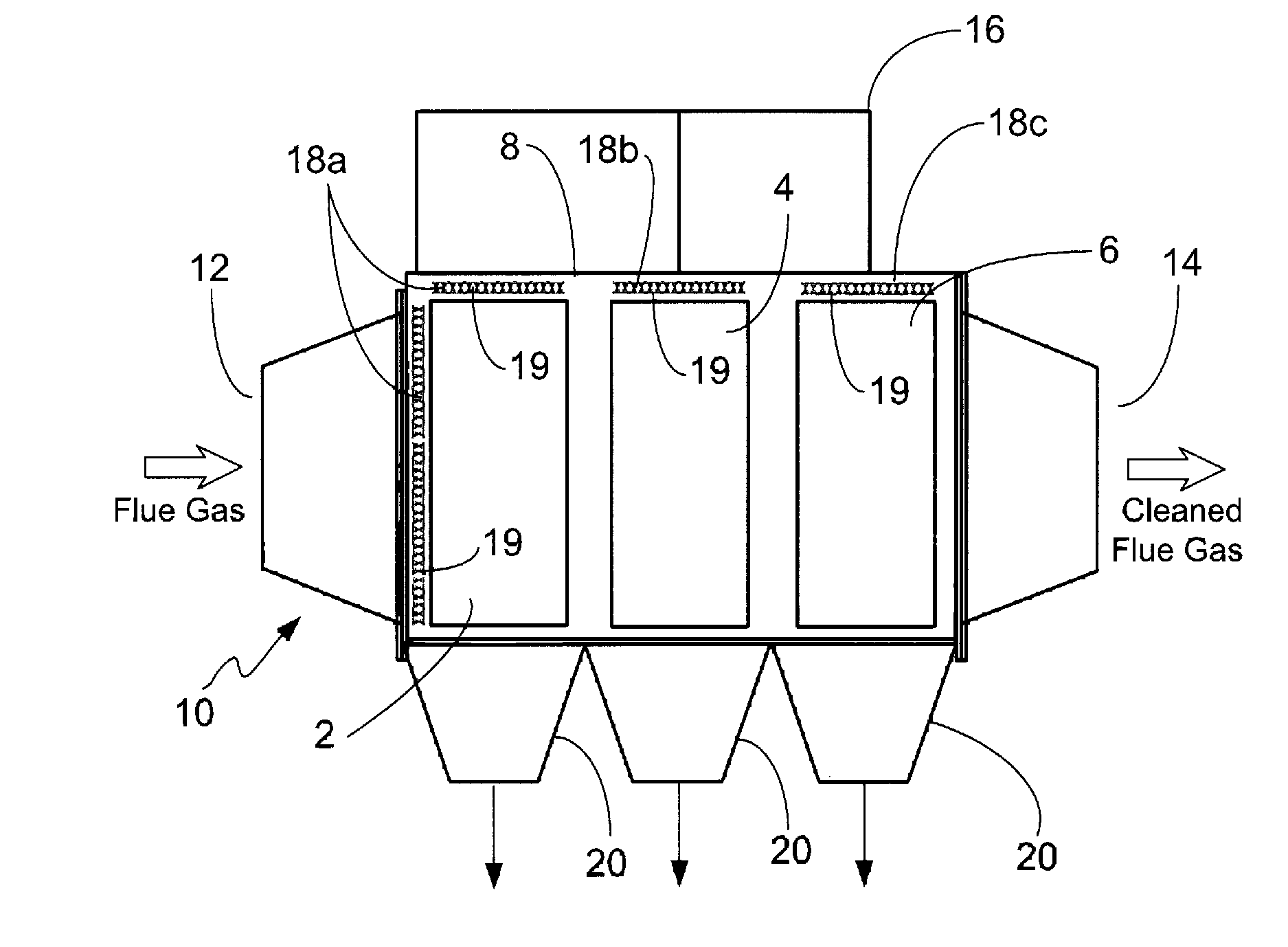
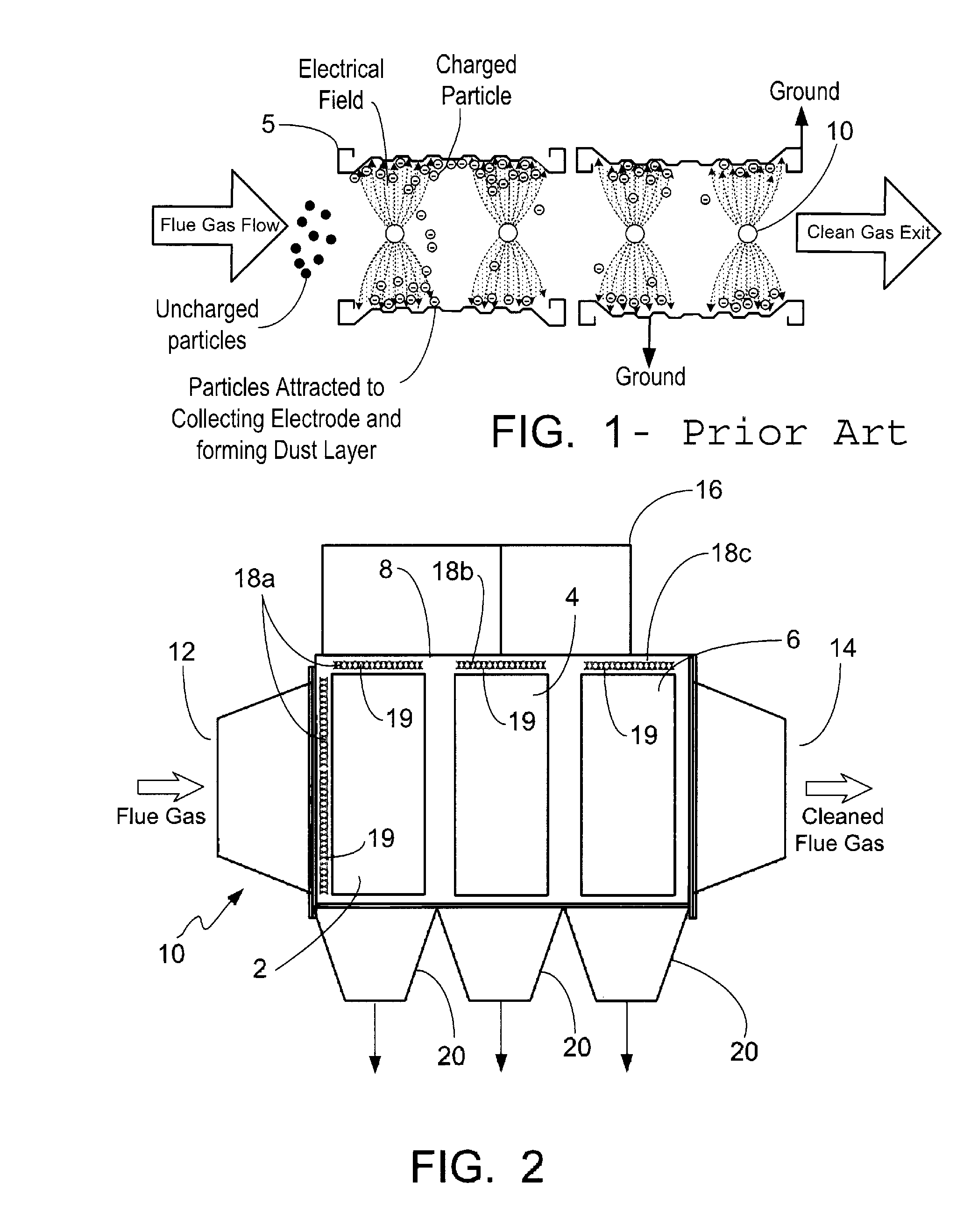
[0019]As shown in FIG. 2, a hybrid, wet electrostatic precipitator 10 has a housing 8, a first electric precipitation zone 2 in the path of the flue gas, a second electric precipitation zone 4 and a third electric precipitation zone 6 which are downstream from the first electric precipitation zone 2. Particulate-laden gas enters the housing 8 at entrance 12 and leaves the housing at exit 14. The electric precipitation zones 2, 4, 6 are in series with each other. As would be appreciated by the skilled artisan for the purposes of the present application, the terms collection zone and electric precipitation zone are synonymous and thus used interchangeably here through.

[0020]Although FIG. 1 shows horizontal gas flow, the HWESP of the instant invention can be configured such that flow can be directed any direction such as and including vertically or diagonally. The number of electric precipitation zones may also be increased or decreased depending upon the specific design requirements.

[...


PUM


Abstract

A hybrid, wet electrostatic precipitator has multiple precipitation zones for removing particulate and contaminants from a flue gas stream. A first precipitation zone has at least one discharge electrode and at least one collection plate made of a metal or a fiber glass reinforced plastic. A second precipitation zone has at least one discharge electrode and at least one collecting electrode which is a porous membrane sheet. The precipitation zones are in series with one another.

Description

FIELD AND BACKGROUND OF INVENTION[0001]The present invention relates generally to the field of flue gas cleanup apparatuses and, in particular, to a new and useful hybrid, wet electrostatic precipitator (HWESP) used to remove particulate and contaminants from exhaust gases.[0002]Electrostatic precipitators (ESPs) are used in coal-fired power plants, the cement industry, mineral ore processing and many other industries to remove particulate from an exhaust gas stream. ESPs are particularly well suited for high efficiency removal of fine particles from a gas stream. Specially designed dry ESPs have attained particle collection efficiencies as high as 99.9%. However, conventional ESP collection efficiencies are at their lowest values for fine particle sizes between 0.1-1.0 microns. Additionally, conventional ESPs cannot address the problem of gaseous emissions or gas-to-particle conversion. The release of substances such as acid gases and mercury from the flue gas generated by the comb...

Claims


Application Information

Patent Timeline
Patent Type & Authority Patents(United States)
IPC IPC(8): B03C3/014
CPCB01D53/32B03C3/08B03C3/16B03C3/025B01D2259/818B03C2201/08
Inventor TRISCORI, RONALD J.MORETTI, ALBERT L.SNYDER, ROBERT E.TONN, DONALD P.
Owner THE BABCOCK & WILCOX CO
Why Eureka
Try Eureka