Tensioner with multiple spring rates

a technology of tensioner and spring rate, applied in the direction of spring/damper functional characteristics, machines/engines, gearing, etc., can solve the problems of parasitic power loss, friction loss, high fuel consumption, etc., and achieve the effect of low tension and higher tension

Active Publication Date: 2015-09-03
LITENS AUTOMOTIVE INC
View PDF17 Cites 18 Cited by
  • Summary
  • Abstract
  • Description
  • Claims
  • Application Information

AI Technical Summary

Benefits of technology

[0005]The actuator may operate to collapse the first resilient element, in which case the stiffness coefficient of the strut is characterized by the stiffness coefficient of the second resilient element. The tensioner will thus provide a relatively lower tension in this condition. Alternatively, the actuator may not compress the first resilie...

Problems solved by technology

Parasitic losses in a typical front engine accessory drive (FEAD) system of a vehicle can contribute to higher fuel consumption.
The initial system belt tension is one of the main contributors to parasitic power losses.
The parasitic losses incurred during operation of the engine include belt losses which are directly relat...

Method used


Image

  • Tensioner with multiple spring rates
  • Tensioner with multiple spring rates
  • Tensioner with multiple spring rates

Examples


Embodiment Construction

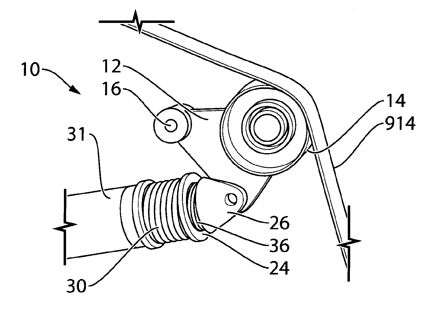
[0042]Reference is made to FIG. 2, which shows a crankshaft 910 from an engine 913 from a vehicle (not shown). It will be noted that the engine 913 is shown as a simple rectangle for illustrative purposes. It will be understood that the engine 913 may have any suitable shape. The vehicle may be any suitable vehicle, such as an automobile, a truck, a van, a minivan, a bus, an SUV, a military vehicle, a boat or any other suitable vehicle.

[0043]The crankshaft 910 has a crankshaft pulley 912 thereon. The crankshaft pulley 912 drives one or more vehicle accessories via a belt 914. The term ‘belt’ is used herein for convenience, however for the purpose of the claims and for the scope of this disclosure it will be understood that the belt 914 may alternatively be any other type of suitable endless drive member. It will further be noted that, in cases where the endless drive member is a belt, it may be any suitable type of belt, such as a flat belt, a V belt, a poly-V belt, a timing belt, o...


PUM


Abstract

In a first aspect, a tensioner is provided which includes: an arm, including a pivot mount; a pulley rotatably mounted to the arm; and a strut pivotally connected to the arm. The strut includes: a base, having a pivot mount; a first body moveable relative to the base; a first resilient element connected between the base and the first body, the first resilient element having a first stiffness coefficient; a second body moveable relative to the first body, the second body having a pivot mount; a second resilient element connected between the first body and the second body, the second resilient element having a second stiffness coefficient that is lower than the first stiffness coefficient; and an actuator, connected to the base and first body, for selectively moving the first body towards the base and compressing the first resilient element.

Description

CROSS-REFERENCE TO RELATED APPLICATIONS[0001]This application claims priority from U.S. Provisional Patent Application No. 61 / 729,492 filed Nov. 23, 2012, from U.S. Provisional Patent Application No. 61 / 767,774 filed Feb. 21, 2013, and from U.S. Provisional Patent Application No. 61 / 895,799, filed Oct. 25, 2013, the contents of all of which are incorporated herein in their entirety.FIELD OF INVENTION[0002]This disclosure relates generally to the field of automatic tensioners for endless drive elements such as chains or belts.BACKGROUND OF INVENTION[0003]Parasitic losses in a typical front engine accessory drive (FEAD) system of a vehicle can contribute to higher fuel consumption. The initial system belt tension is one of the main contributors to parasitic power losses. In heavy truck applications (for example, on highway class 8 trucks), it is often the power requirements of the engine fan that drive the required belt tension. (For example in large transport trucks, a typical large ...

Claims


Application Information

Patent Timeline
IPC IPC(8): F16H7/12F02B67/06
CPCF16H7/1281F02B67/06F16H2007/0893F16H2007/0806F16H2007/0865F16H7/1218F16H2007/0812F16H2007/0823F16F15/067F16F1/121F16F3/04F16F2228/08
Inventor GRAVES, GARRETH
Owner LITENS AUTOMOTIVE INC
Why Eureka
Try Eureka