Supercharge Your Innovation With Domain-Expert AI Agents!

Orthodontic anchor screw device

a technology screw body, which is applied in the field of orthodontic anchoring screw device, can solve the problem of not being able to align one orthodontic anchoring screw relative to the other,

Inactive Publication Date: 2015-09-10
BUDDEMEYER DARREN E +1
View PDF22 Cites 2 Cited by
  • Summary
  • Abstract
  • Description
  • Claims
  • Application Information

AI Technical Summary

Benefits of technology

The present disclosure is about an orthodontic anchor screw device that can be easily inserted into a jaw bone and used to treat any number of teeth. This device can be temporarily screwed into the bone to counteract rotational movement and can work with other orthodontic appliances for alignment or other teeth corrective purposes. The technical effects of this patent are that it provides a reliable and effective treatment option for orthodontic patients and a simple way to manage any rotational movement that may occur during the treatment process.

Problems solved by technology

Although orthodontic anchoring screws are useful, there is no way to align one orthodontic anchoring screw relative to another.

Method used


Image

  • Orthodontic anchor screw device
  • Orthodontic anchor screw device

Examples


Embodiment Construction

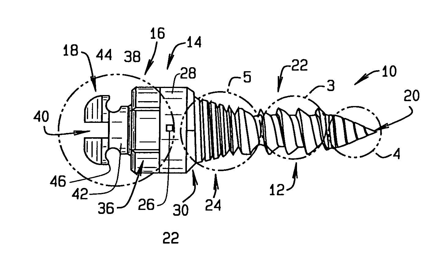
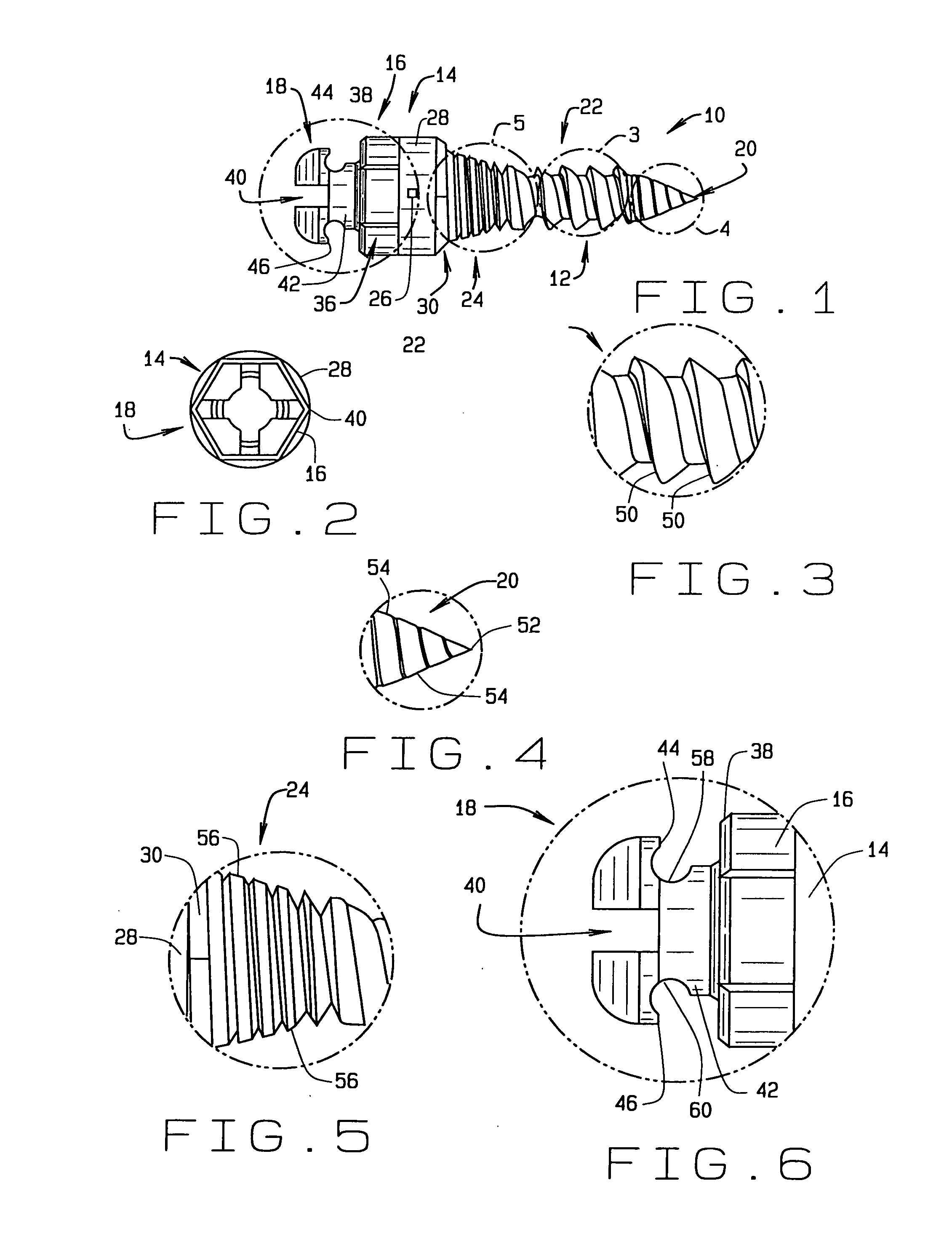
[0022]Referring now to the drawings, wherein like numbers refer to like items, number 10 identifies a preferred embodiment of an orthodontic anchor screw device constructed according to the present disclosure. With reference now to FIG. 1, the orthodontic anchor screw device 10 comprises a threaded barrel like section 12, a first transition area 14, a second transition area 16, and a screw head 18. The threaded barrel section 12 has a cutting end 20, a coarsely threaded section 22, and a finely threaded section 24. The cutting point 20 is for cutting through a gum of an individual and into a jaw bone for anchoring the device 10. The first transition area 14 has an alignment marking 26 placed on a side 28 of the first transition area 14. The alignment marking 26 is used to align one of the devices 10 relative to another device 10 to perform an orthodontic installation procedure. A sloped or chamfer transition area 30 is positioned between the threaded barrel section 12 and the first ...


PUM


Abstract

An orthodontic anchor screw device is disclosed in which the device comprises a threaded barrel section, a first transition area having an alignment marking, a second transition area, and a screw head.

Description

CROSS REFERENCE TO RELATED APPLICATION[0001]This non-provisional patent application claims priority to the provisional patent application having Ser. No. 61 / 967,153, filed on Mar. 10, 2014.FIELD OF THE DISCLOSURE[0002]This disclosure generally relates to orthodontic devices for assisting in orthodontic treatments or procedures, and more particularly to an orthodontic anchor screw device for use in orthodontic correction treatments or procedures.BACKGROUND[0003]Orthodontists treat patients by controlling the movement and displacement of teeth in a mouth by use of various orthodontic devices and procedures. Movement or rotation of a tooth within the mouth may be accomplished through the use of external forces applied to the tooth. To ensure that the moved or treated tooth remains in a desired location in the jaw bone, an external force is applied to the tooth for an extended period of time. Once the tooth has reached a desired position or orientation, the force may be removed. Some ex...

Claims


Application Information

Patent Timeline
Patent Type & Authority Applications(United States)
IPC IPC(8): A61C8/00
CPCA61C8/0025A61C8/0096
Inventor BUDDEMEYER, DARREN E.KIM, KI BEOM
Owner BUDDEMEYER DARREN E
Features
  • R&D
  • Intellectual Property
  • Life Sciences
  • Materials
  • Tech Scout
  • Unparalleled Data Quality
  • Higher Quality Content
  • 60% Fewer Hallucinations
Learn More