
Robot, robot system, control device, and control method

Active Publication Date: 2015-09-10
SEIKO EPSON CORP +1
View PDF28 Cites 15 Cited by
  • Summary
  • Abstract
  • Description
  • Claims
  • Application Information

AI Technical Summary

Benefits of technology

The present invention aims to solve the issues in the assembly work method by providing a robot that can perform good assembly work. The robot system, control device, and control method have been designed to improve the efficiency and accuracy of assembly work.

Problems solved by technology

However, in the method of the related art, when a position of the rotation center is changed with a relative position between the gripping unit and the manipulation target as the manipulation target comes in contact with the assembly target during work, the change in the position of the rotation center cannot be detected and good assembly work may not be performed.

Method used


Image

  • Robot, robot system, control device, and control method
  • Robot, robot system, control device, and control method
  • Robot, robot system, control device, and control method

Examples


first embodiment

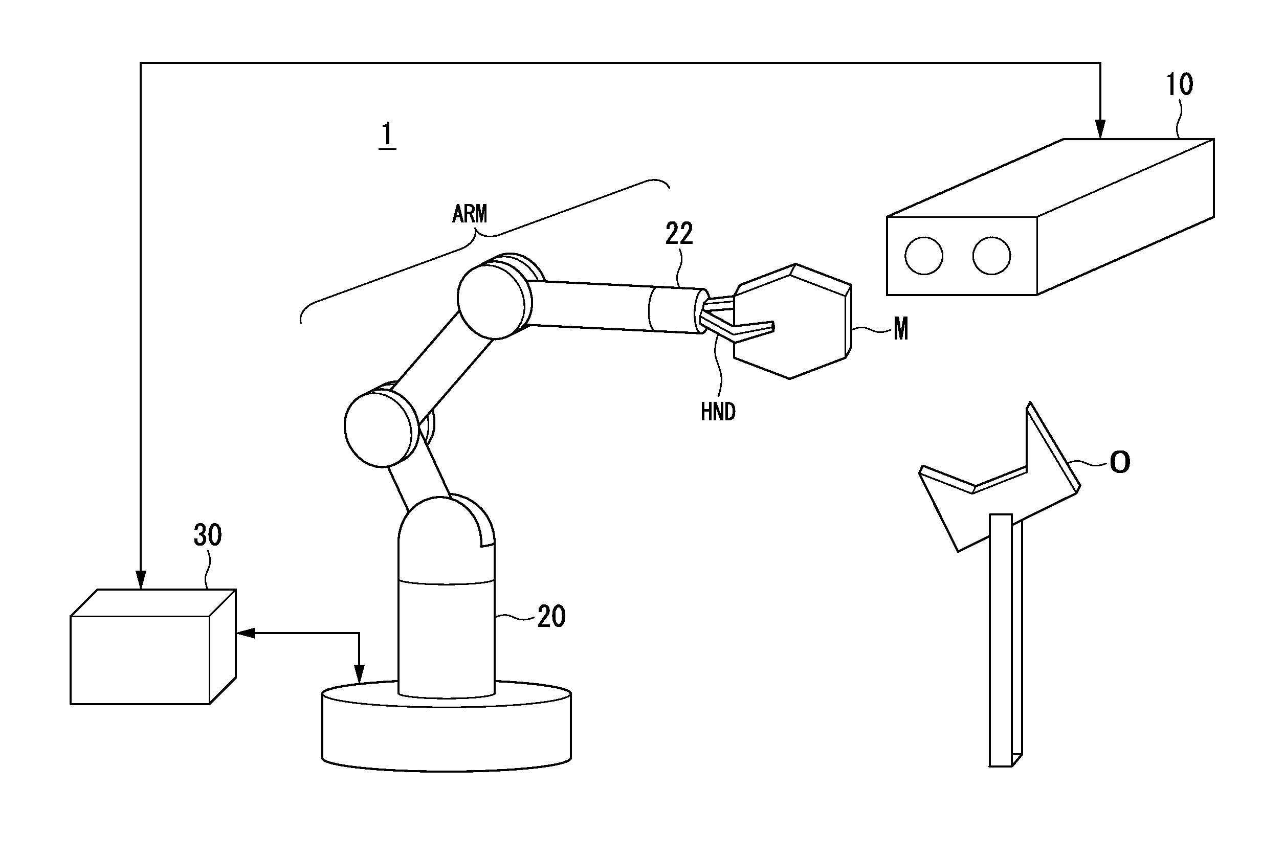
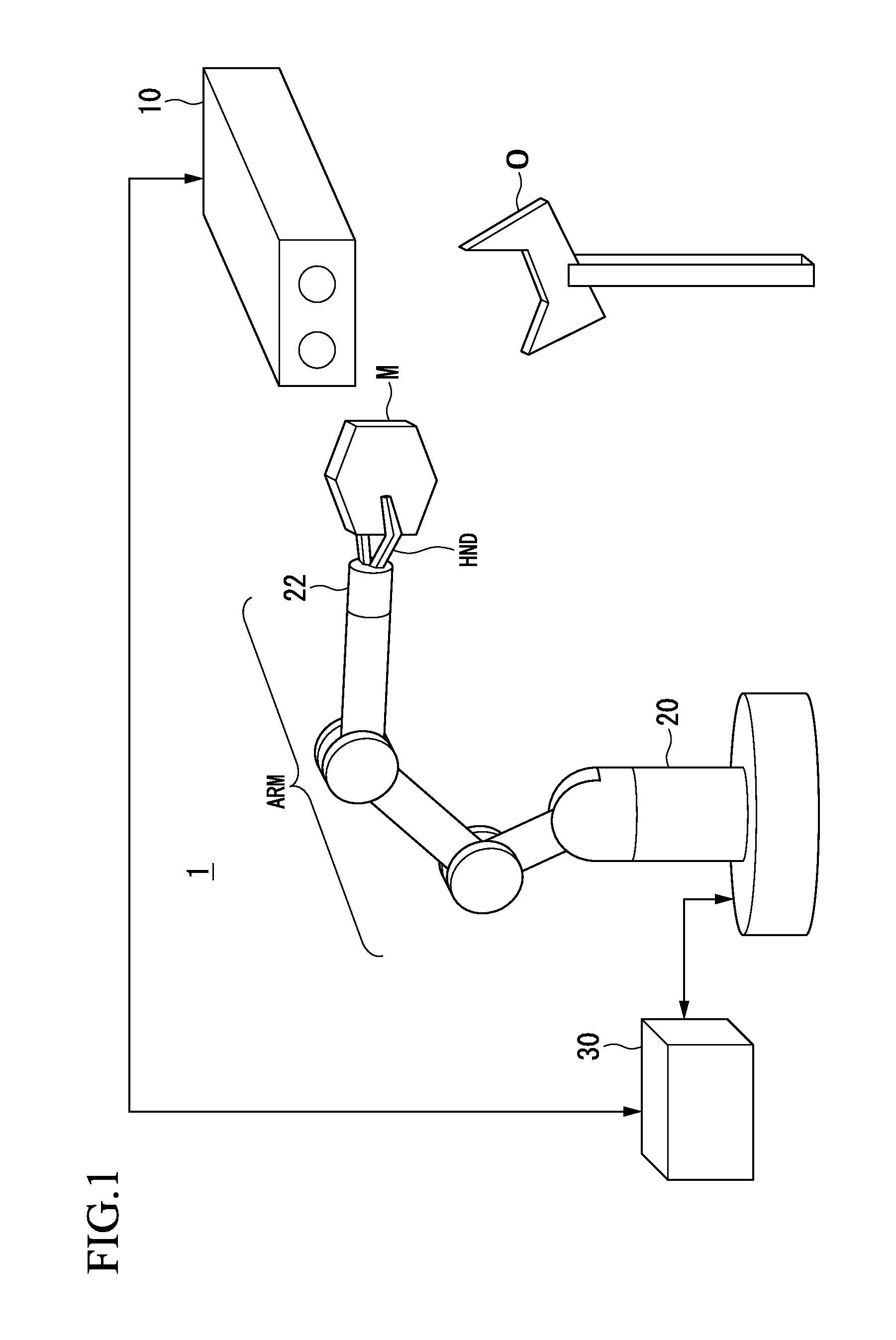
[0041]Hereinafter, a first embodiment of the present invention will be described with reference to the drawings. FIG. 1 is a configuration diagram illustrating an example of a robot system 1 according to the first embodiment. The robot system 1 includes an imaging unit 10, a robot 20, and a control device 30.

[0042]The imaging unit 10 is, for example, a camera including a CCD (Charge Coupled Device) or a CMOS (Complementary Metal Oxide Semiconductor) which is an imaging element that converts condensed light into an electrical signal. Further, the imaging unit 10 is a stereo camera including two cameras, but may include, for example, three or more cameras or may have a configuration in which a two-dimensional image is captured by one camera.

[0043]The imaging unit 10 is connected to the control device 30 via a cable so that the imaging unit 10 can communicate with the control device 30. For example, wired communication via the cable is performed according to a standard such as Ethernet...

second embodiment

[0134]Hereinafter, a second embodiment of the present invention will be described with reference to the drawings. The robot system 2 according to the second embodiment may have a configuration in which a dual-arm robot is included as the robot 25, in place of the configuration in which the single arm robot is included as the robot 20. Further, in the second embodiment, the same constituent units as those in the first embodiment are denoted with the same reference signs.

[0135]FIG. 6 is a configuration diagram illustrating an example of the robot system 2 according to the second embodiment. The robot system 2 includes an imaging unit 10, a robot 25, and a control device 30.

[0136]In the second embodiment, an assembly target O is installed on a stand such as a table by a jig or the like, and a manipulation target M is assembled through the predetermined work described in the first embodiment, by any one arm of the robot 25 which is a dual-arm robot. Further, the assembly target O may be...

third embodiment

[0142]Hereinafter, a third embodiment of the present invention will be described with reference to the drawings. Further, in the third embodiment, the same constituent units as in the first embodiment are denoted with the same reference signs. In predetermined work, a robot system 1 according to the third embodiment assembles, for example, a wrench (an example of a manipulation target M) gripped by a gripping unit HND and a bolt (an example of an assembly target O), and then tightens the bolt with the gripped wrench.

[0143]Here, the predetermined work performed by the robot system 1 according to the third embodiment will be described with reference to FIGS. 7A to 7D. FIGS. 7A to 7D are diagrams schematically illustrating an example of the predetermined work performed by the robot system 1 according to the third embodiment. FIG. 7A illustrates a state of a predetermined initial position before a wrench M1 gripped by the robot 20 is assembled with a bolt O1. The robot system 1 moves th...


PUM


Abstract

Provided is a robot including a hand and a control unit that operates the hand. The control unit rotates a first object around a predetermined position of the first object with the hand and moves the first object with respect to a second object, based on a captured image including the hand and the first object.

Description

CROSS-REFERENCE TO RELATED APPLICATIONS[0001]Priority is claimed on Japanese Patent Application No. 2014-045752, filed Mar. 7, 2014, the content of which is incorporated herein by reference.BACKGROUND OF THE INVENTION[0002]1. Field of the Invention[0003]The present invention relates to a robot, a robot system, a control device, and a control method.[0004]2. Description of the Related Art[0005]A technology for performing compliant motion control of a robot based on information acquired by a force sensor, which is information on a force acting on a gripping unit of the robot or a manipulation target gripped by the gripping unit, and a captured image imaged by an imaging unit has been researched and developed.[0006]In connection with this, for example, a control device that controls a robot to maintain a motion characteristic set for each axis of compliant motion control in an initial state and perform good assembly work even when a posture for an manipulation target is changed during ...

Claims


Application Information

Patent Timeline
IPC IPC(8): B25J9/16
CPCB25J9/1612G05B2219/39543G05B2219/39487B25J9/1697B25J9/1687G05B2219/39346G05B2219/39394G05B2219/39483G05B2219/40583
Inventor NAMMOTO, TAKASHIKOSUGE, KAZUHIROHASHIMOTO, KOICHI
Owner SEIKO EPSON CORP
Learn More