
Front structure of vehicle body

Inactive Publication Date: 2015-09-10
TOYOTA JIDOSHA KK
View PDF38 Cites 20 Cited by
  • Summary
  • Abstract
  • Description
  • Claims
  • Application Information

AI Technical Summary

Benefits of technology

The objective of this patent is to create a front structure for a vehicle body that can absorb more of the impact from collisions, while still allowing space for all the necessary components to be stored on-board.

Problems solved by technology

This will affect the capacity for accommodating on-board components.

Method used


Image

  • Front structure of vehicle body
  • Front structure of vehicle body
  • Front structure of vehicle body

Examples


Embodiment Construction

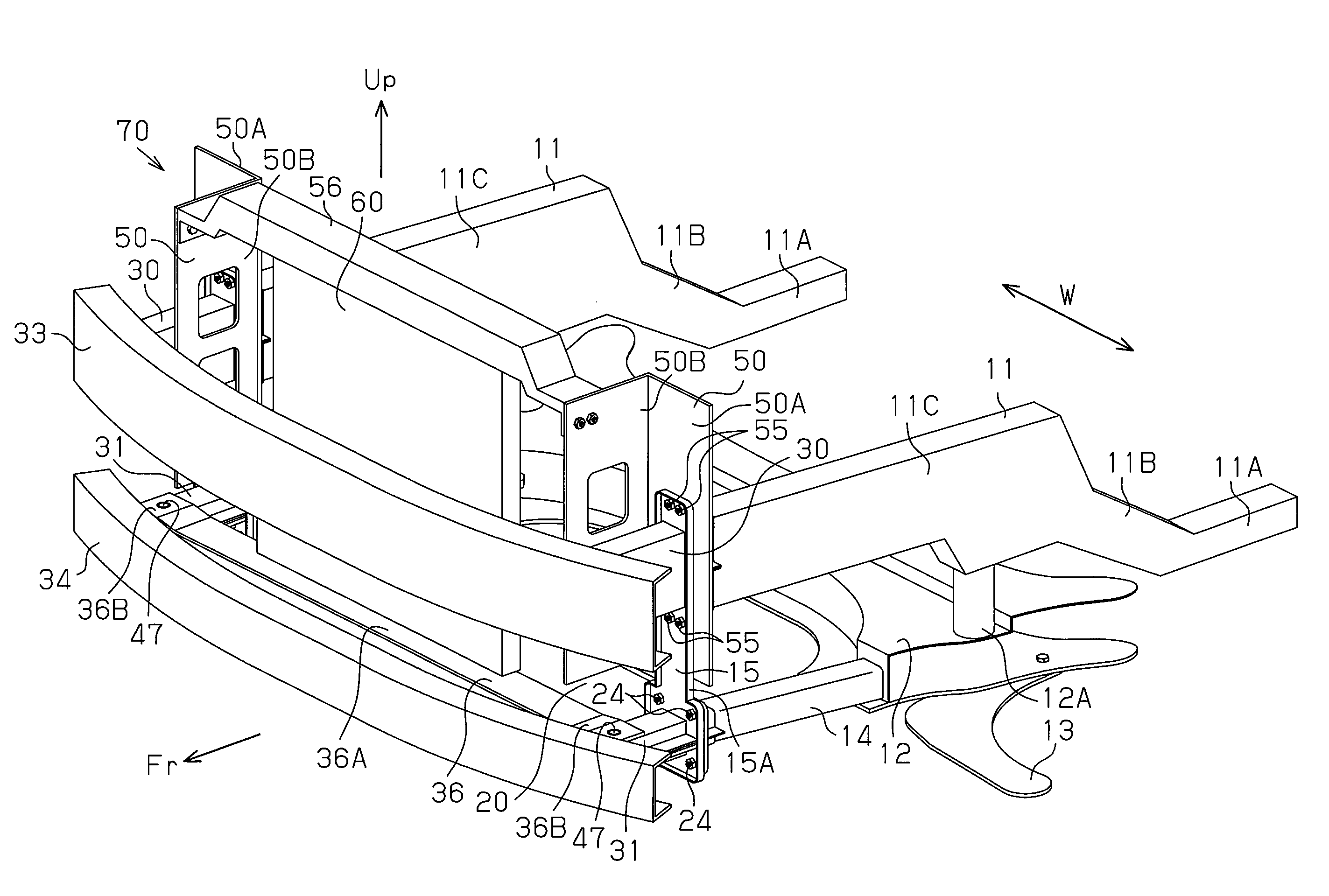
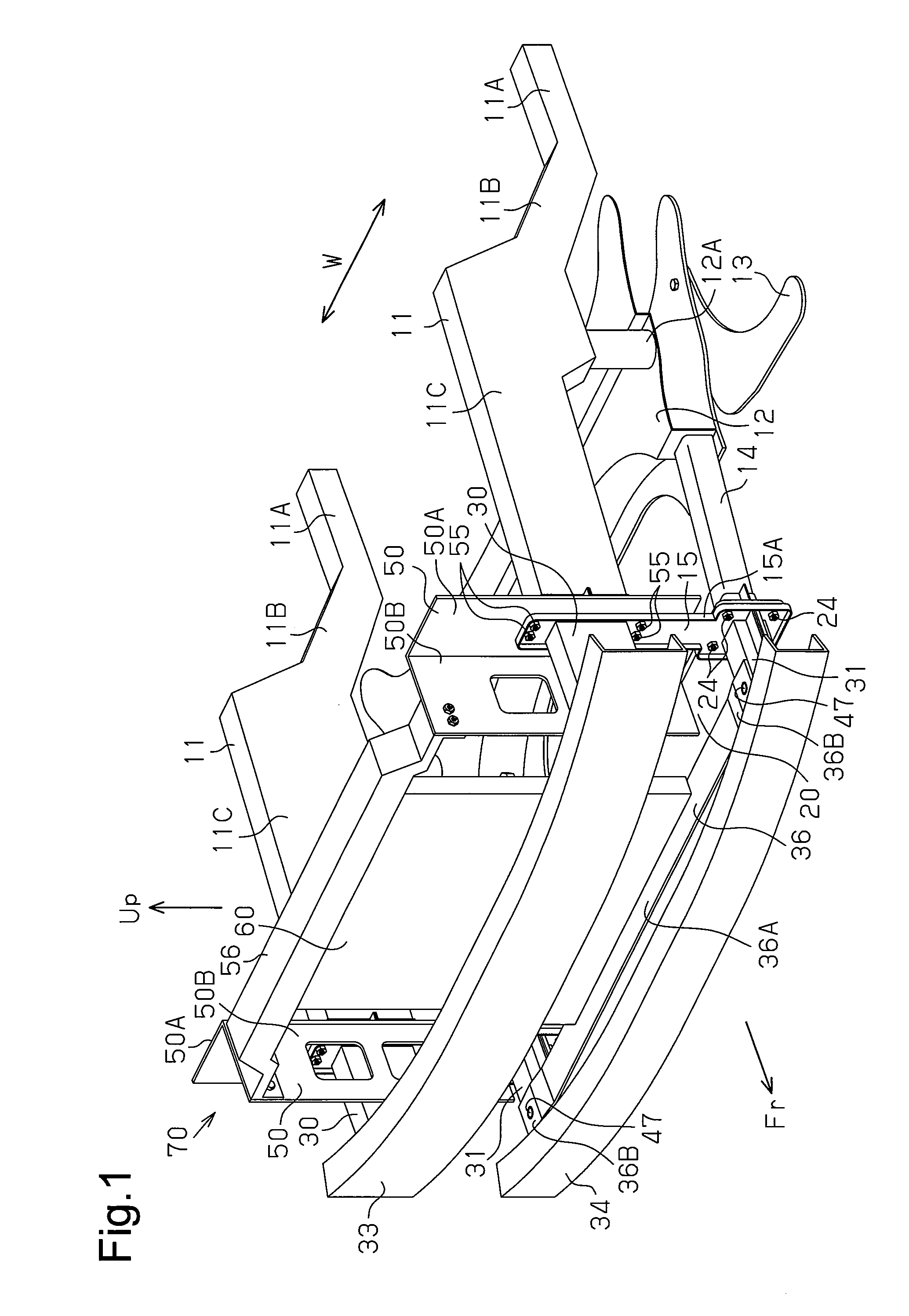
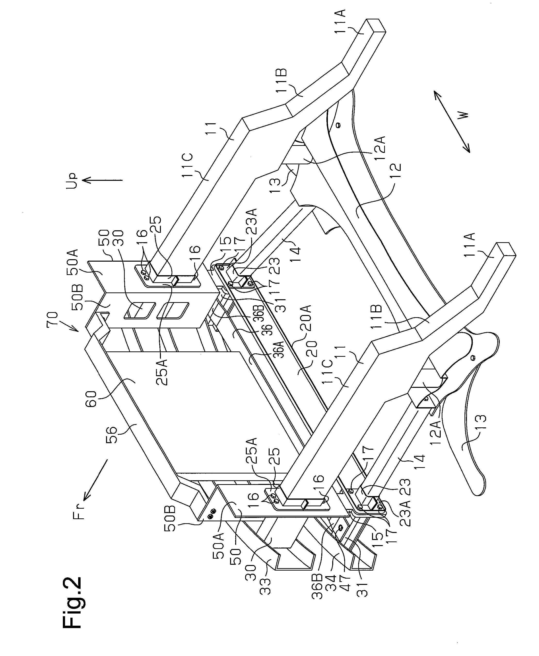
[0019]One embodiment of a front structure of a vehicle body will now be described with reference to the drawings. In the drawings, arrow Fr indicates the front direction as viewed from the vehicle body, arrow Up indicates the upper direction as viewed from the vehicle body, and arrow W indicates the lateral direction of the vehicle body.

[0020]As shown in FIGS. 1 and 2, a front structure of a vehicle body includes two side frames 11 located at the two lateral sides of the vehicle body. Each side frame 11 is formed by a metal tetragonal tube and includes a rear portion 11A, which is coupled to the vehicle body and extended toward the rear of the vehicle body, a sloped portion 11B, which extends diagonally upward toward the front of the vehicle body from the front end of the rear portion 11A, and a front portion 11C, which extends toward the front of the vehicle body from the front end of the sloped portion 11B.

[0021]A suspension member 12 is coupled from the lower side to the side fra...


PUM


Abstract

A front structure of a vehicle body includes a first bumper reinforcement extending in a lateral direction of the vehicle body. A second bumper reinforcement extends in the lateral direction of the vehicle body below the first bumper reinforcement. Two first crash boxes are coupled to the two ends of the first bumper reinforcement. Two second crash boxes are coupled to the two ends of the second bumper reinforcement. Two vertical posts are coupled to the rear ends of the first and second crash boxes. Two side frames are coupled to the two vertical posts opposite to the first crash boxes. Two lower members are coupled to the two vertical posts opposite to the second crash boxes. A lower support member couples the second crash boxes to each other and forms a lower portion of a radiator support.

Description

BACKGROUND OF THE INVENTION[0001]The present invention relates to a front structure of a vehicle body that absorbs collision load applied from the front of a vehicle body.[0002]Japanese Laid-Open Patent Publication No. 2009-40187 describes a bumper device that is one example of a front structure of a vehicle body. As shown in FIG. 9, the bumper device 100 includes a first bumper reinforcement 101 and a second bumper reinforcement 102, which extend in the lateral direction of a vehicle body. First crash boxes 103 (only one shown in the drawing), which extend in the longitudinal direction of the vehicle body, are coupled to the two ends of the first bumper reinforcement 101. Second crash boxes 104 (only one shown in the drawing), which extend in the longitudinal direction of the vehicle body, are coupled to the two ends of the second bumper reinforcement 102. A side member 105, which forms a portion of the vehicle body, is coupled to the rear end of each first crash box 103 with a sid...

Claims


Application Information

Patent Timeline
IPC IPC(8): B60R19/18B60R19/12
CPCB60R19/18B60R2019/1813B60R19/12B60R19/34B62D21/152B62D25/082
Inventor MORI, TAKEO
Owner TOYOTA JIDOSHA KK
Learn More