Crankcase oil catcher

a crankcase oil catcher and crankcase technology, applied in the direction of cylinders, mechanical equipment, machines/engines, etc., can solve the problems of oil returning from the cylinder head may lose heat, oil may lose heat, etc., to achieve large surface area, increase viscosity, and heat loss

Active Publication Date: 2015-09-10
FORD GLOBAL TECH LLC
View PDF1 Cites 4 Cited by
  • Summary
  • Abstract
  • Description
  • Claims
  • Application Information

AI Technical Summary

Benefits of technology

[0003]During warm up of an internal combustion engine, the engine block structure acts as a large heat sink because the thermal inertia of the engine block structure is an order of magnitude greater than the coolant and oil. For this reason, the engine block structure may take longer to warm up than the oil. By way of example, hot oil returning from a piston cooling gallery, which has been heated by combustion events, may hit a crank of the engine and the oil may be thrown against the cooler crankcase. When oil is thrown against the crankcase wall, the oil may lose heat due to the large thermal inertia and large surface area of the crankcase. Similarly, oil returning from the cylinder head has been heated and may lose heat upon returning through the engine block to the oil sump. The resulting colder oil has a higher viscosity, which may lead to higher frictional losses, and in turn, higher fuel consumption and / or a reduced cabin heating.

Problems solved by technology

When oil is thrown against the crankcase wall, the oil may lose heat due to the large thermal inertia and large surface area of the crankcase.
Similarly, oil returning from the cylinder head has been heated and may lose heat upon returning through the engine block to the oil sump.
The resulting colder oil has a higher viscosity, which may lead to higher frictional losses, and in turn, higher fuel consumption and / or a reduced cabin heating.
The systems above, thus, lack an ability to reduce thermal losses due contact interactions between oil and the engine block structure.
Specifically, heated engine oil may still hit an engine crank and even be thrown against the crankcase wall, which leads to higher frictional losses, and increases the duration of time for oil heating in some instances.

Method used


Image

  • Crankcase oil catcher
  • Crankcase oil catcher
  • Crankcase oil catcher

Examples


Embodiment Construction

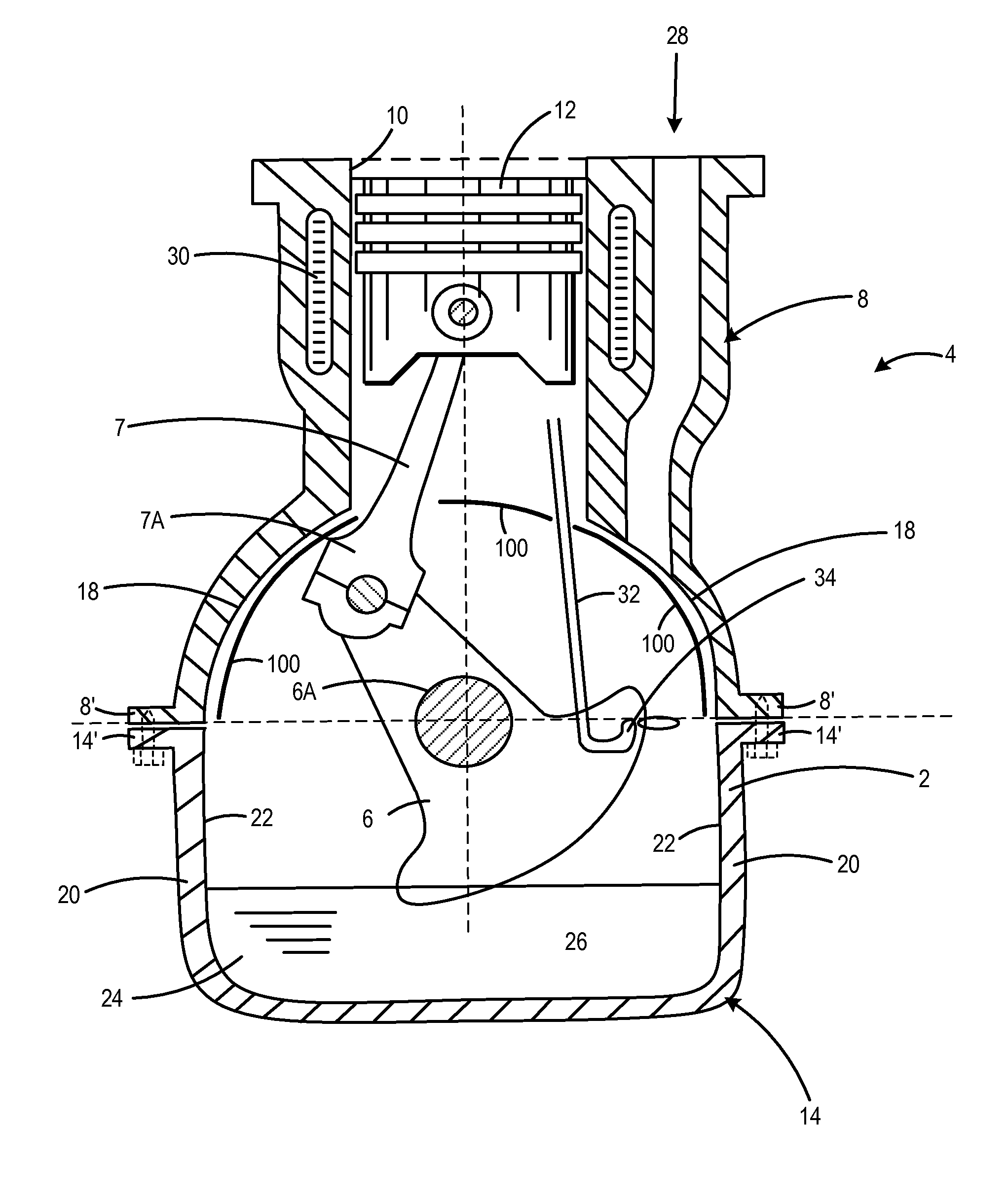
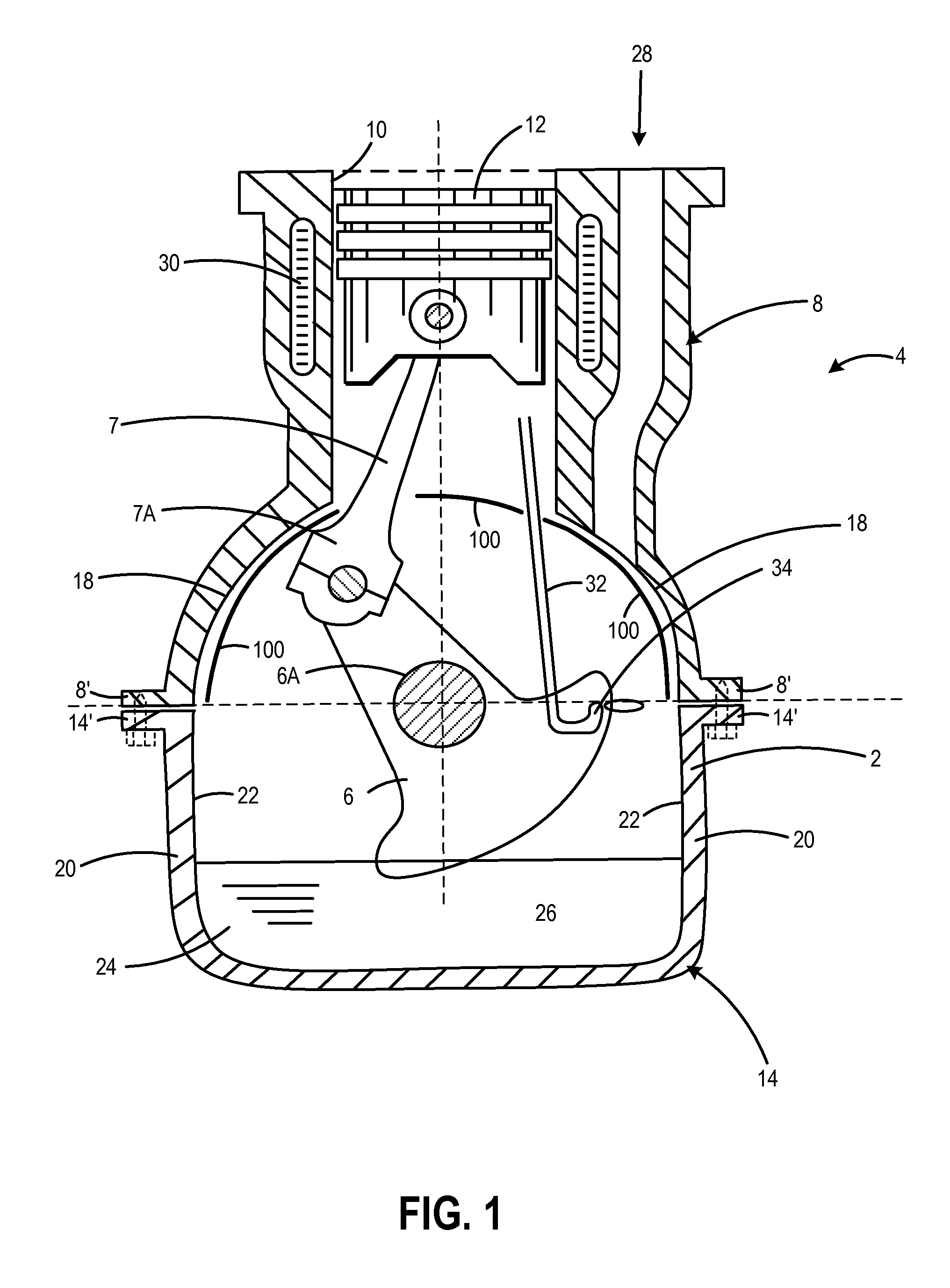
[0013]The present description relates to an engine with a crankcase oil catcher. In other words, an engine, such as an internal combustion engine, may comprise the above-mentioned crankcase oil catcher. Similarly, a vehicle, such as an automobile, van or any other motor vehicle, may comprise the above-mentioned crankcase oil catcher. A crankcase oil catcher according to the present disclosure is configured to be provided for a single cylinder of an engine. In other words, one crankcase oil catcher may be provided per piston. In some instances, the crankcase oil catcher may be configured to be provided between walls between neighboring cylinders of the engine. However, it is also envisaged that the crankcase oil catcher may extend beneath a plurality of pistons.

[0014]Herein, the crankcase oil catcher is described with respect to one cylinder, although the engine may comprise one or more cylinders within a crankcase that are arranged above a crankshaft extending through the crankcase....


PUM


Abstract

A crankcase oil catcher configured for placement above a crankshaft and below a piston is described. In one particular example, the crankcase oil catcher has a contour that catches dispersed oil within the crankcase while directing the oil away from a casing wall and towards a crank sump along the contoured surface of the crankcase oil catcher. Inclusion of an aperture within the surface allows for passage of a connecting rod of the crankshaft while providing for a protruding lip around the perimeter of the aperture that prevents oil on the top surface from falling through the aperture.

Description

CROSS REFERENCE TO RELATED APPLICATIONS[0001]The present application claims priority to Great Britain Patent Application No. 1404205.5, entitled “Crankcase Oil Catcher,” filed Mar. 10, 2014, the entire contents of which are hereby incorporated by reference for all purposes.FIELD[0002]The present description relates to a crankcase oil catcher, and in particular, but not exclusively, a crankcase oil catcher configured to catch dispersed oil in a crankcase and direct the oil towards a crank sump and away from a crankcase casing wall.BACKGROUND AND SUMMARY[0003]During warm up of an internal combustion engine, the engine block structure acts as a large heat sink because the thermal inertia of the engine block structure is an order of magnitude greater than the coolant and oil. For this reason, the engine block structure may take longer to warm up than the oil. By way of example, hot oil returning from a piston cooling gallery, which has been heated by combustion events, may hit a crank o...

Claims


Application Information

Patent Timeline
Patent Type & Authority Applications(United States)
IPC IPC(8): F01M11/00F01P3/08
CPCF01M11/0004F01P3/08F01M2011/0091F01P2003/006F01M2011/0033
Inventor PEGG, IAN GRAHAMSTARK, ROLAND PAUL
Owner FORD GLOBAL TECH LLC
Why Eureka
Try Eureka