Standing pole type LED light

a technology of led light and standing pole, which is applied in the direction of semiconductor devices for light sources, coupling device connections, lighting and heating apparatus, etc., can solve the problems of poor safety and inconvenient assembly operation, and achieve the effects of simple fixing structure, enhanced safety, and convenient operation

Inactive Publication Date: 2015-09-10
XIAMEN STAR ELECTRICAL EQUIP
View PDF14 Cites 7 Cited by
  • Summary
  • Abstract
  • Description
  • Claims
  • Application Information

AI Technical Summary

Benefits of technology

[0013]With the above arrangement, the present invention uses the two vertical clamping surfaces of the right-angled clamp plates to securely fix the LED light board so as to expand the contact area therebetween, making it more stable and secured. To assemble, the LED light board is first fixed by the right-angled clamp plates and then, the right-angled clamp plates and the LED light board are collectively deposited into the heat sink to be fixed therein. The LED light board is connected to the driver circuit and then, the LED light board is inserted into the vertical reflection pole. The operation is easy. Further, the plastic housing is directly injection-molded on a surface of the metal-made heat sink and there is no gap and no medium existing therebetween. The plastic housing helps prevent electrical leaking and heating and enhances safety.
[0014]The present invention makes the fixing structure of the LED light board simple and has a strong feeling of integrity and a low cost.

Problems solved by technology

The LED light board is clamped by the top faces of the left half and the right half and is fixed by means of bolts so that the contact area is small, the fixing is not secured, and the assembling operation is inconvenient.
This makes it possible for the heat sink to leak electricity and get heated, making the safety poor.

Method used


Image

  • Standing pole type LED light
  • Standing pole type LED light
  • Standing pole type LED light

Examples


Embodiment Construction

[0021]The following descriptions are exemplary embodiments only, and are not intended to limit the scope, applicability or configuration of the invention in any way. Rather, the following description provides a convenient illustration for implementing exemplary embodiments of the invention. Various changes to the described embodiments may be made in the function and arrangement of the elements described without departing from the scope of the invention as set forth in the appended claims.

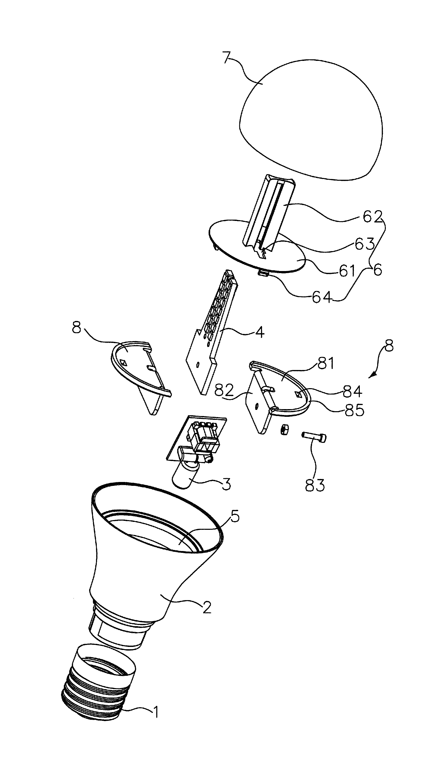
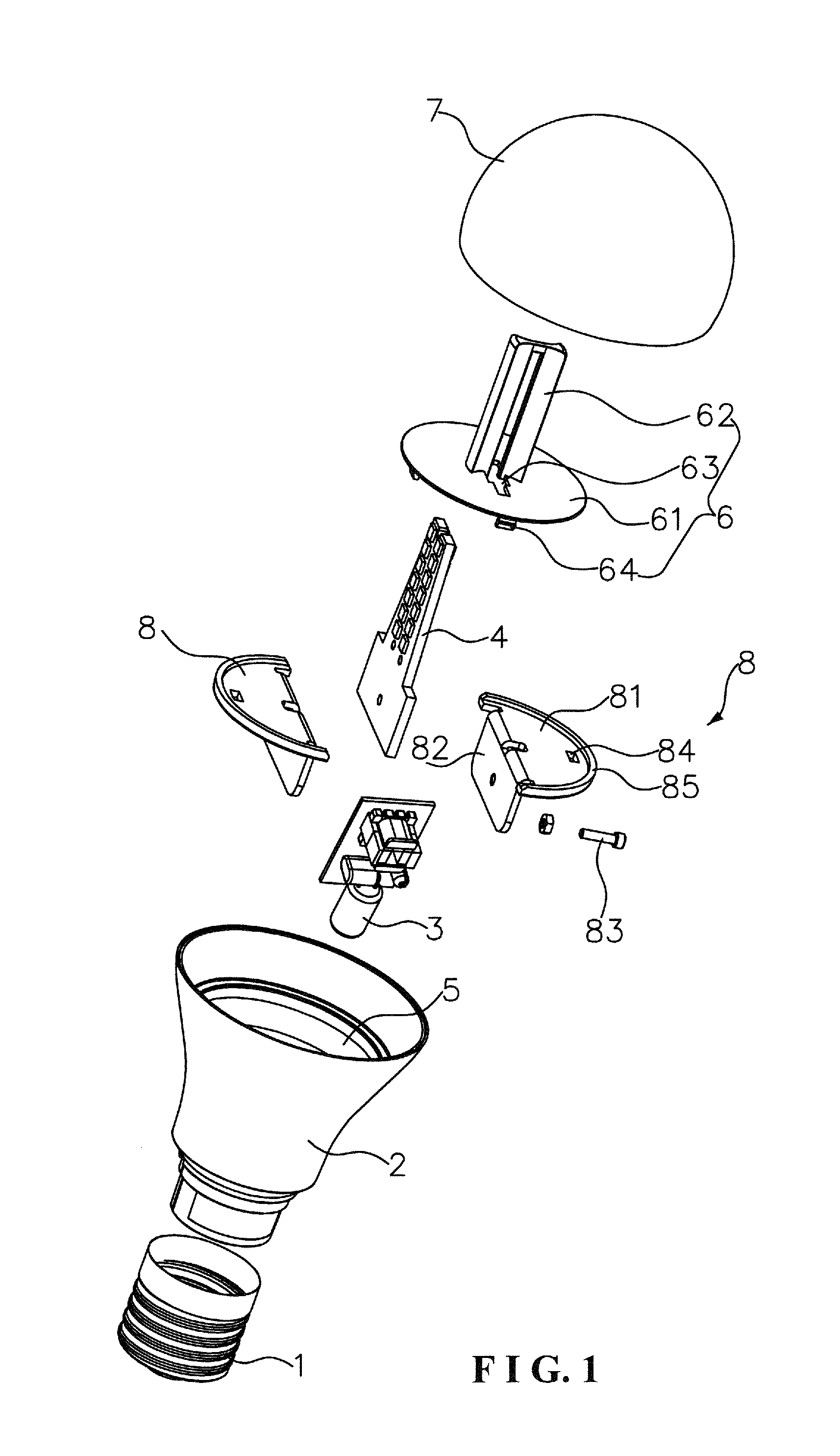
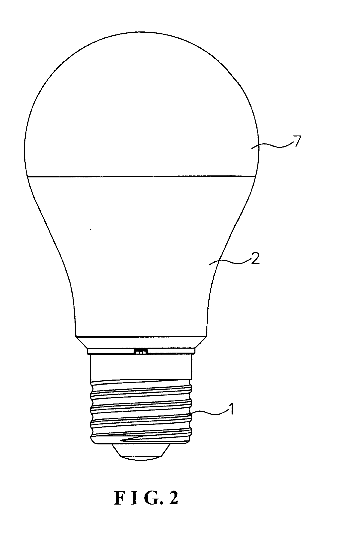
[0022]As shown in FIGS. 1-4, the present invention discloses a standing pole type LED light, which comprises a base 1, a plastic housing 2, a driver circuit 3, an LED light board 4, right-angled clamp plates 8, a heat sink 5, a vertical reflection pole 6, and a cover 7.

[0023]The plastic housing 2 is formed through direct injection-molding of a polycarbonate material on a surface of the aluminum-made heat sink 5 and, after injection molding, may have a preferred thickness of 0.1-2 mm that covers the ...


PUM


Abstract

A standing pole type LED light includes a plastic housing directly injection molded on a surface of a heat sink and both of them being mounted to a base. Two right-angled clamp plates have vertical clamping surfaces that are securely fixed to opposite sides of a lower portion of an LED light board and horizontal carrying surfaces mounted to the wide opening of the heat sink. The vertical reflection pole has four curved reflection faces that are arranged to stand on the reflection base in a symmetric manner. The reflection base is mounted to the horizontal carrying surfaces. The LED light board is inserted between the four curved reflection faces and is connected via a driver circuit mounted in the heat sink to the base. The cover is mounted to a top end of the plastic housing.

Description

(a) TECHNICAL FIELD OF THE INVENTION[0001]The present invention generally relates to an LED (Light-Emitting Diode) light, and more particularly to a standing pole type LED light.(b) DESCRIPTION OF THE PRIOR ART[0002]At the present, a standing pole type LED light is available and is made up of a base, a driver circuit, an LED light board, a heat sink, a vertical reflection pole, and a cover. The base receives the heat sink to mount thereon and the heat sink is composed of a left half and a right half coupled to each other. The vertical reflection pole comprises a reflection base and four curved reflection faces. The four curved reflection faces (arc surfaces) are arranged to stand on the reflection base in a symmetric manner. The reflection base is mounted to the heat sink. The driver circuit is mounted in the heat sink. The LED light board is inserted between the four curved reflection faces of the vertical reflection pole. The LED light board has a lower portion that is clamped bet...

Claims


Application Information

Patent Timeline
Patent Type & Authority Applications(United States)
IPC IPC(8): F21V29/00F21V23/00F21K99/00
CPCF21V29/22F21K9/50F21V23/004F21K9/135F21K9/232F21V23/006F21K9/238
Inventor LI, GUANGHUI
Owner XIAMEN STAR ELECTRICAL EQUIP
Why Eureka
Try Eureka