Ultrasonic sensor

a technology of ultrasonic sensor and sensor body, applied in the field of ultrasonic sensor, can solve the problems of poor workability, excessively small opening portion, and reduced efficiency, and achieve excellent mass productivity, enhanced transmission and reception, and high aspect ratio

Active Publication Date: 2015-09-17
SEIKO EPSON CORP
View PDF1 Cites 23 Cited by
  • Summary
  • Abstract
  • Description
  • Claims
  • Application Information

AI Technical Summary

Benefits of technology

[0005]An advantage of some aspects of the invention is to provide an ultrasonic sensor in which efficiency of transmission and reception is enhanced, or in which an ultrasonic sensor of which mass productivity is excellent by causing deformation of a piezoelectric element in a film thickness direction to be significant, even if an opening portion has a high aspect ratio, or even if the size of the shape of an opening portion is greater than that of an active portion of a piezoelectric element.

Problems solved by technology

However, if the shape of the opening portion is caused to be the same size as the active portion of the piezoelectric element, partitions forming the opening portion inhibit propagation of ultrasonic waves, an efficiency decreases or a size of the opening portion becomes excessively small so that workability becomes worse.
In addition, the “rectangular shape” may not be a perfect rectangular shape, and includes substantially rectangular shapes of which corners may be rounded, or sides may be uneven.

Method used


Image

  • Ultrasonic sensor
  • Ultrasonic sensor
  • Ultrasonic sensor

Examples


embodiment 1

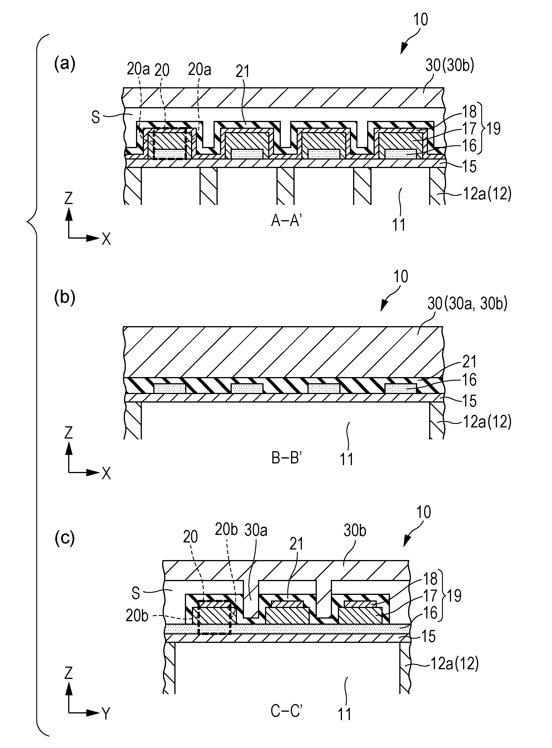
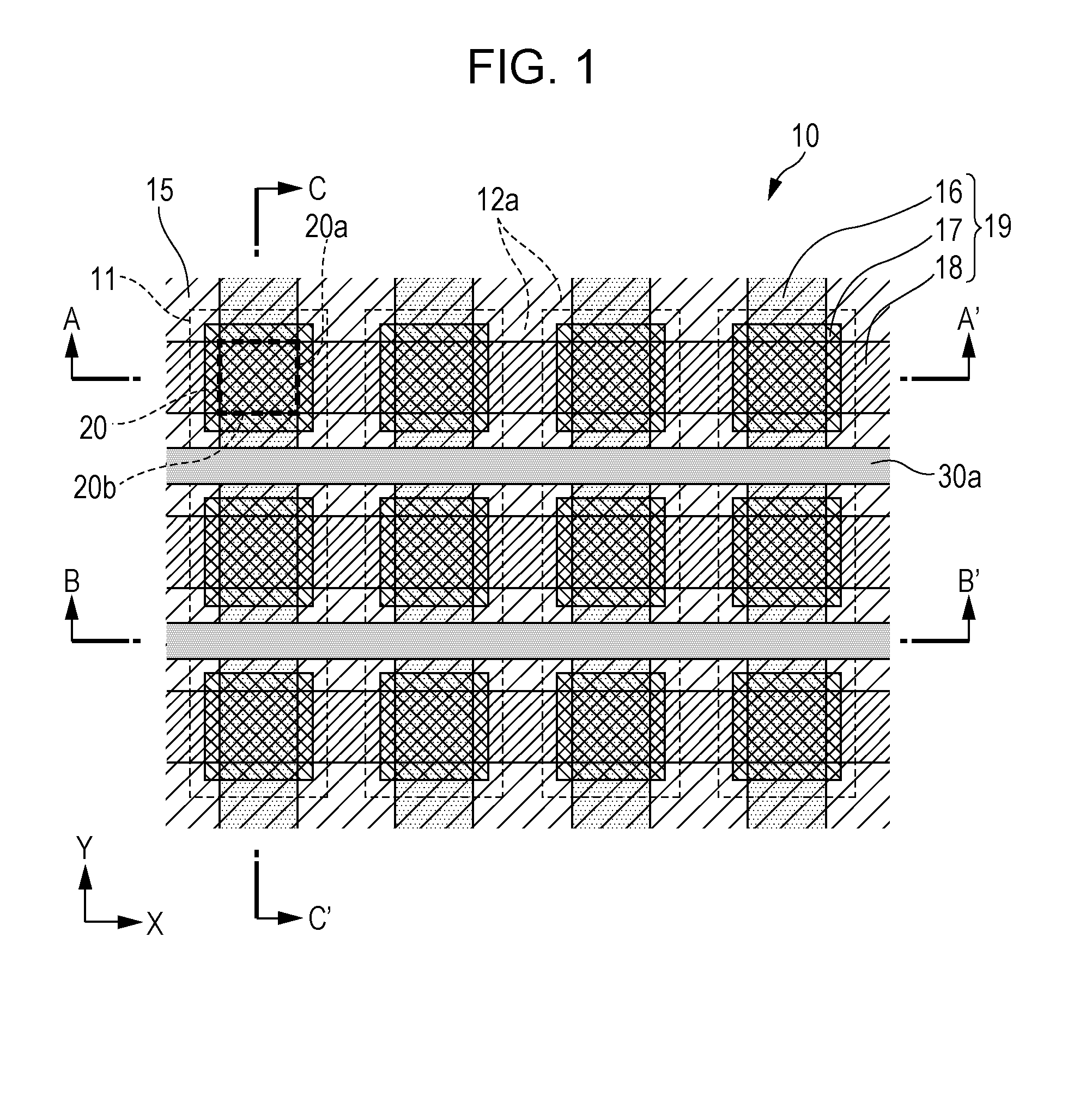
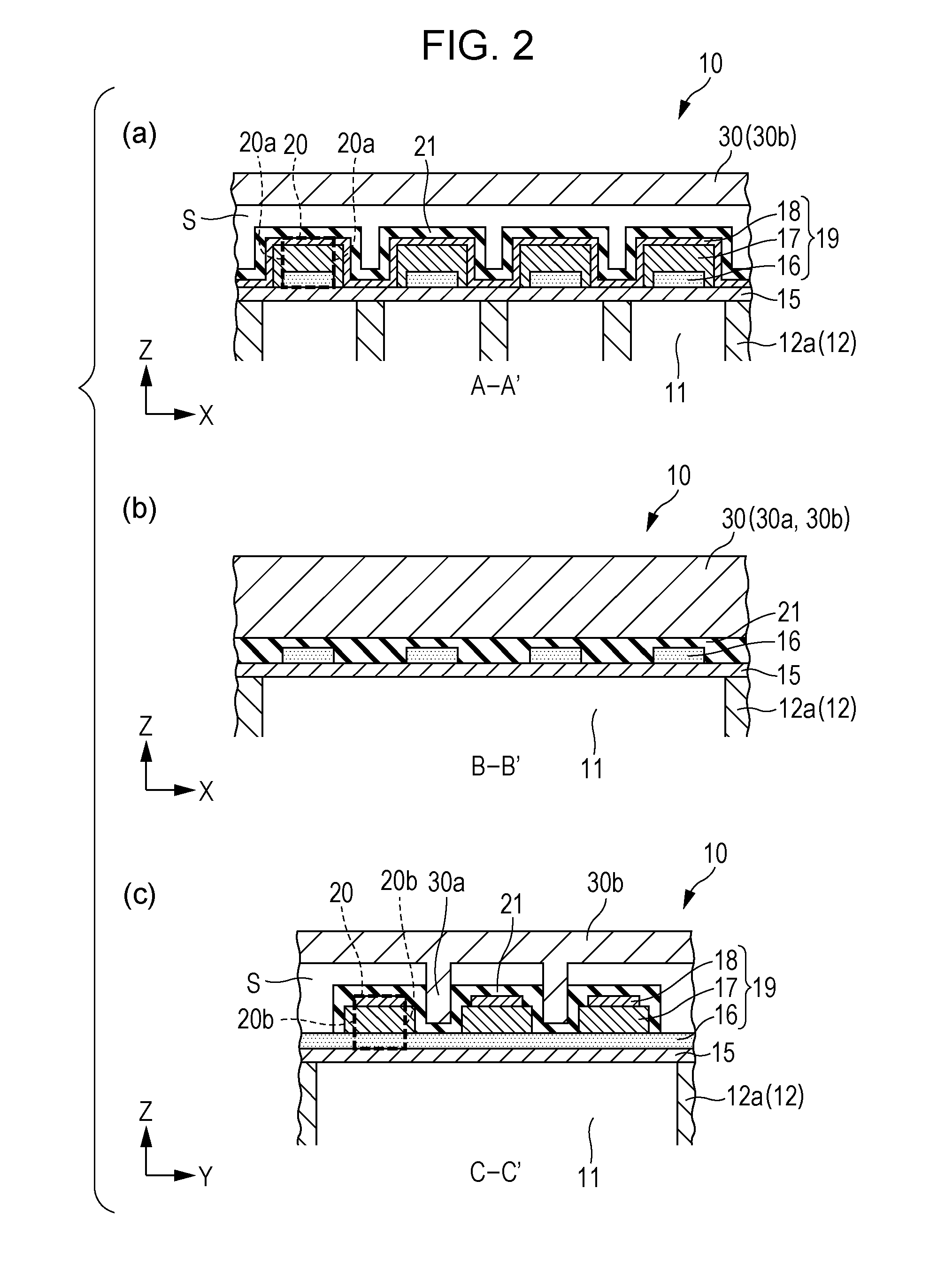
[0024]FIG. 1 is a plan view schematically illustrating a configuration of an ultrasonic sensor according to Embodiment 1 of the invention, FIG. 2(a) is a sectional view taken along line A-A′ of FIG. 1, FIG. 2(b) is a sectional view taken along line B-B′ of FIG. 1, and FIG. 2(c) is a sectional view taken along line C-C′ of FIG. 1.

[0025]As illustrated in FIGS. 2(a) to 2(c), an ultrasonic sensor 10 of Embodiment 1 includes a substrate 12 on which an opening portion 11 is formed, a vibration plate 15 provided on the substrate 12 blocking the opening portion 11, and a piezoelectric element 19 including a first electrode 16, a piezoelectric layer 17 and a second electrode 18 which are stacked on the opposite side of the opening portion 11 of the vibration plate 15. A portion which is completely overlapped by the first electrode 16, the piezoelectric layer 17, and the second electrode 18 in the film thickness direction Z is called an active portion 20. The substrate 12 is formed of silicon...

embodiment 2

[0044]In Embodiment 1, the column portion 30a is provided in the sealing plate 30, but a metal layer 35 may be provided on the substrate 12 (the vibration plate 15) instead of providing the column portion 30a in the sealing plate 30, and a suppressing portion may be formed by the metal layer 35. As the material of the metal layer 35, gold, copper, aluminum, or the like can be employed. When wiring is formed on the substrate 12, the metal layer can be formed of the same material as the wiring and at the same time of forming the wiring. Considering that the metal layer can be formed of the same material as the wiring and at the same time of forming the wiring, gold is preferable in view of conductivity.

[0045]If the metal layer 35 is provided on the substrate 12 (the vibration plate 15), the corresponding metal layer 35 functions as a weight. Though the effect is more decreased than that in Embodiment 1, the metal layer 35 functions as the suppressing portion in the same manner as in E...

embodiment 3

[0049]In the embodiments described above, the ultrasonic sensor 10 includes the opening portions 11 of which the aspect ratio is great, but the size is relatively small. In Embodiment 3, an ultrasonic sensor 10A including opening portions 11A of which the aspect ratio is small, but the size is very large is described.

[0050]FIG. 5 is a plan view schematically illustrating a configuration of an ultrasonic sensor according to Embodiment 3, FIG. 6(a) is a sectional view taken along line D-D′ of FIG. 5, FIG. 6(b) is a sectional view taken along line E-E′ of FIG. 5, and FIG. 6(c) is a sectional view taken along line F-F′ of FIG. 5.

[0051]In FIGS. 5 and 6, the same elements as in Embodiment 1 are denoted by the same reference numerals, and the repetitive descriptions are omitted.

[0052]As illustrated in FIG. 5, the opening portion 11A has a smaller aspect ratio that the opening portion 11 (FIG. 1) of Embodiment 1 in a planar view. However, the size of the opening portion 11A is much larger t...


PUM


Abstract

An ultrasonic sensor includes a substrate on which an opening portion is formed; a vibration plate that is provided on the substrate so as to block the opening portion; and a piezoelectric element including a first electrode, a piezoelectric layer, and a second electrode that are stacked on an opposite side of the opening portion of the vibration plate, in which when a direction in which the first electrode, the piezoelectric layer, and the second electrode are stacked is set to be a Z direction, and a portion that is completely overlapped by the first electrode, the piezoelectric layer, and the second electrode in the Z direction is set to be an active portion, the plural active portions are provided so as to face the one opening portion, and a suppressing portion (column portion) that suppresses vibrations of the vibration plate is provided between the adjacent active portions.

Description

TECHNICAL FIELD[0001]The present invention relates to an ultrasonic sensor.BACKGROUND ART[0002]In the related art, there is known an ultrasonic sensor including a semiconductor substrate having an opening portion, two layers of electrodes on an insulating film layer formed on the surface of the semiconductor substrate by blocking the opening portion, and a piezoelectric element formed with a PZT ceramics thin layer interposed between the two layers of electrodes (see JP-A-2010-164331).[0003]The efficiency of transmission and reception of the ultrasonic sensor depends on the deformation distribution in the ultrasonic sensor, but if it is desired to cause the deformation in the film thickness direction to be significant, a two-dimensional shape when the ultrasonic sensor is viewed in the film thickness direction may be caused to have a low aspect ratio.[0004]Examples of a structure of the ultrasonic sensor include a structure in which transmission and reception are performed on an ope...

Claims


Application Information

Patent Timeline
Patent Type & Authority Applications(United States)
IPC IPC(8): B06B1/06
CPCB06B1/0622G10K11/002
Inventor KOJIMA, CHIKARA
Owner SEIKO EPSON CORP
Why Eureka
Try Eureka