Laser Centering of Robotic Arm

a robotic arm and laser technology, applied in the field of tubes, can solve the problems of damaging the tool, unable to successfully insert the tool into the desired hole in the tubesheet,

Active Publication Date: 2015-09-17
CORESTAR INT
View PDF1 Cites 34 Cited by
  • Summary
  • Abstract
  • Description
  • Claims
  • Application Information

AI Technical Summary

Benefits of technology

[0028]The system can include the one or more lasers are positioned about an exterior of the guide-tube.
[0029]The system can include a controller operative for controlling: movement of the robot to position the tool in alignment with each of a plurality of holes, one-at-a-time, based on camera images of a pattern of laser light formed by the projection of the one or more laser beams on the t

Problems solved by technology

Because of this parallax, it is not uncommon to misalign the tool and a hole in a tubesheet, whereupon the tool cannot be successfully inserted into the desired hole in the tubesheet because of this misalignment.
Because the insertion of the tool into each

Method used


Image

  • Laser Centering of Robotic Arm
  • Laser Centering of Robotic Arm
  • Laser Centering of Robotic Arm

Examples


Embodiment Construction

[0040]The present invention will be described with reference to the accompanying figures where like reference numbers correspond to like elements.

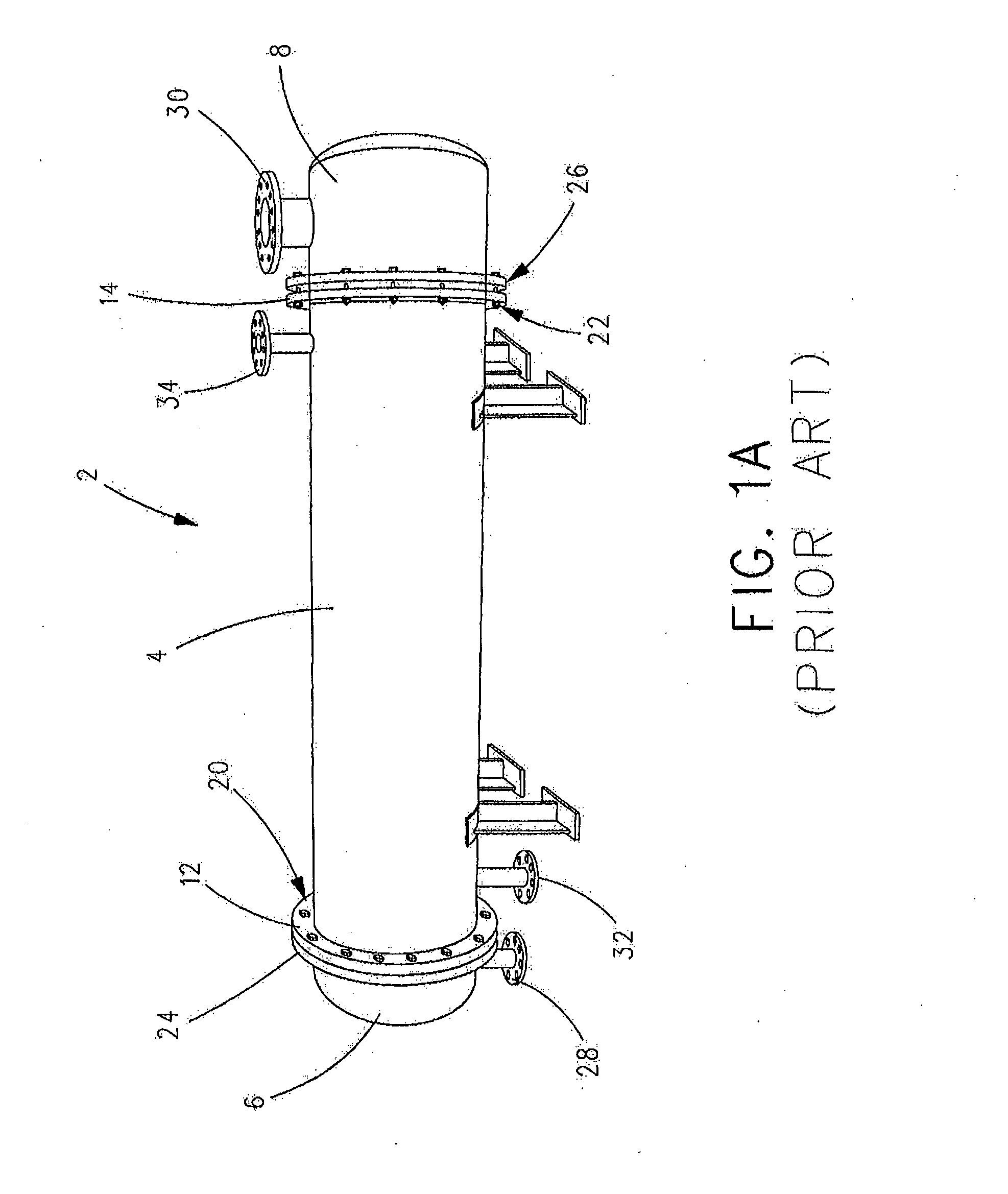
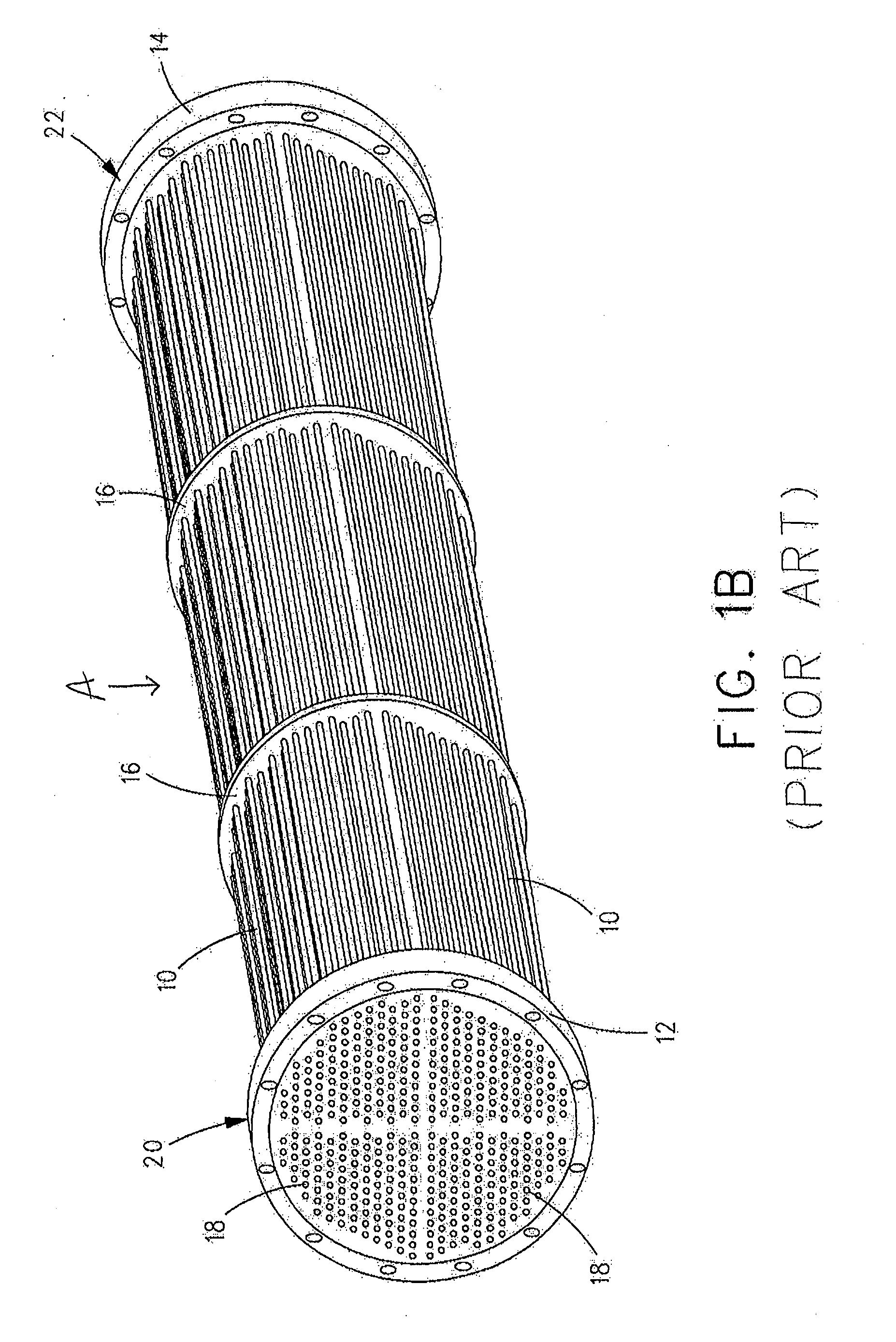
[0041]With reference to FIGS. 1A-C, an industrial liquid-to-liquid heat exchanger 2 found in many industrial applications, such as, without limitation, a nuclear steam generation power plant, includes an elongated cylindrical housing 4 with end caps 6 and 8 coupled to opposite ends of housing 4. Disposed within housing 4 is an internal assembly A that includes a plurality of heat exchange tubes 10 that are held in spaced relation by tubesheets 12 and 14 at opposite ends of tubes 10 and optionally one or more support plates 16 positioned between tubesheets 12 and 14.

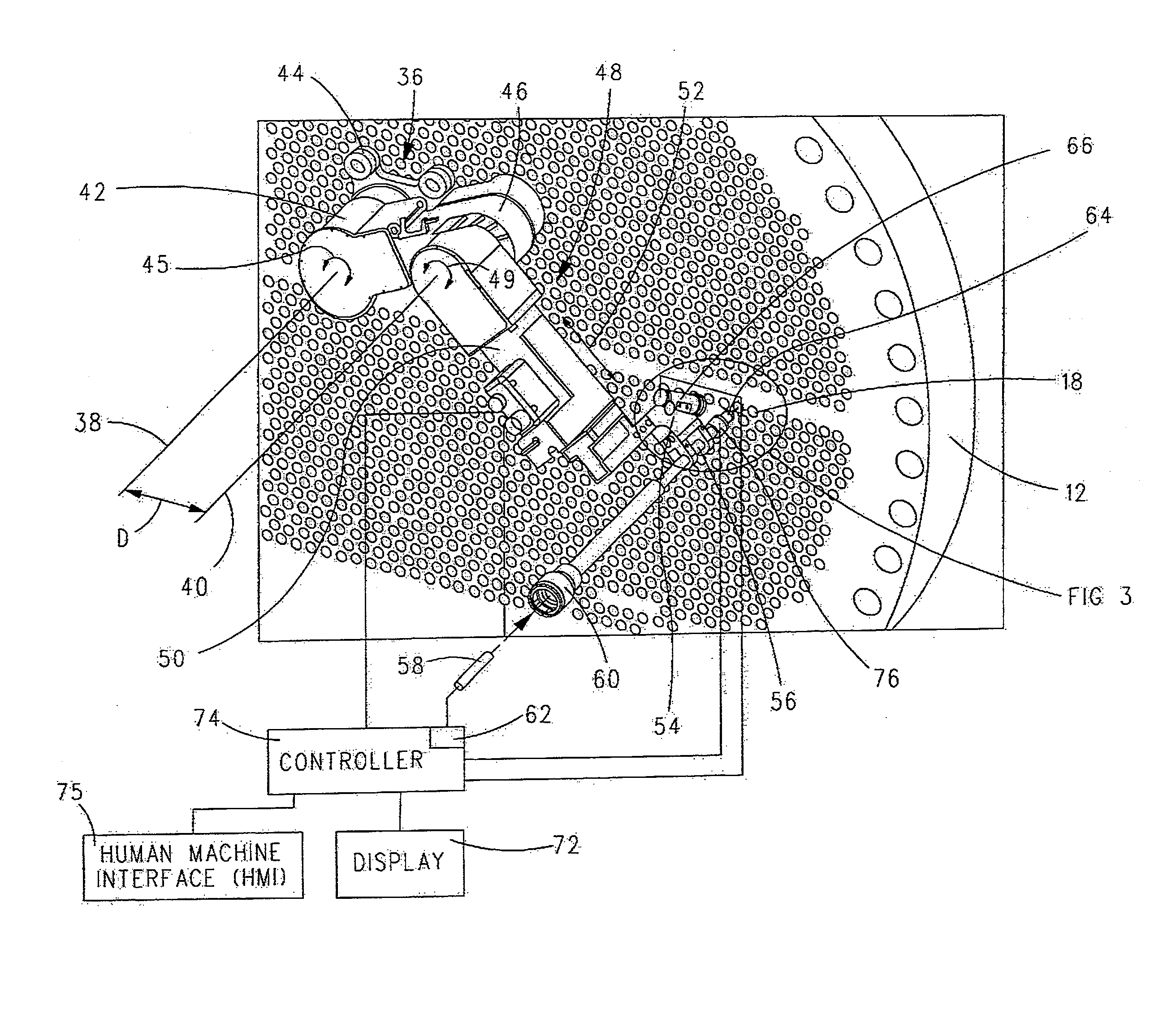
[0042]Each tubesheet 12 and 14 includes a plurality of holes 18 that extend therethrough. Each hole 18 is in fluid communication with one of the tubes 10. Tubesheets 12 and 14 include flanges 20 and 22 that are configured to mate with flanges 24 and 26 of end caps 6 and 8, respe...


PUM

PropertyMeasurementUnit
Coloraaaaaaaaaa
Symmetryaaaaaaaaaa

Abstract

In a system and method of working tubes coupled to a tubesheet having a number of holes, wherein each hole in fluid communication with one of the tubes, an end-effector is positioned by a robot in coarse or rough alignment with a first hole in the tubesheet. Via lasers positioned on the end-effector, laser spots are formed on a surface of the tubesheet adjacent the first hole. The laser spots are detected by a camera and the alignment of the end-effector relative to the first hole in the tubesheet is refined via the robot based on the detected pattern of laser spots. The tool is then moved into the tube that is in fluid communication with the first hole in the tubesheet to work on (inspect, plug, sleeve or weld) the tube.

Description

CROSS REFERENCE TO RELATED APPLICATION[0001]This application claims the benefit of U.S. Provisional Application No. 61 / 952,354, filed Mar. 13, 2014, which is incorporated herein by reference.BACKGROUND OF THE INVENTION[0002]1. Field of the Invention[0003]The present invention relates to working of tubes coupled to a tubesheet and, more particularly, to the use of robotics and light sources for such working.[0004]2. Description of Related Art[0005]In nuclear steam generator and balance of plant eddy current inspections, robots are often used to position a tool in alignment with one or more given tubes, one-at-a-time, in a tubesheet. The robot has an end-effector that supports the tool in position to be fed into holes in the tubesheet. The tool must be positioned directly in alignment with the tube to be inspected in order for the tool to run smoothly through the hole in a tubesheet and into the tube in fluid communication with the hole in the tubesheet.[0006]Typically, a camera mount...

Claims


Application Information

Patent Timeline
IPC IPC(8): B25J19/02B25J18/00F28F99/00
CPCB25J19/023B25J18/00F28F99/00B25J9/1015B25J19/022G01N27/902F01K5/02F28G1/163F28G15/08Y10T29/49352Y10T29/53113
Inventor HAND, DAVID A.BELVILLE, CHRISTOPHER M.CORADI, MICHAEL D.
Owner CORESTAR INT
Why Eureka
Try Eureka