Biological measurement apparatus and a biological measurement method

a biological object and measurement apparatus technology, applied in the field of biological measurement apparatus and biological measurement method, can solve the problems of inability to accurately detect the concentration of blood components, and inability of infrared sensor units to accurately receive infrared light that reflects information regarding biological objects, etc., to achieve favorable precision

Inactive Publication Date: 2015-09-24
SEIKO EPSON CORP
View PDF0 Cites 15 Cited by
  • Summary
  • Abstract
  • Description
  • Claims
  • Application Information

AI Technical Summary

Benefits of technology

[0018]According to this application example, the correction unit corrects the light intensity data using data indicating the force with which the infrared sensor unit and the biological object are pressed together, the light intensity data, and a table indicating the relationship between the force and correction amounts for the light intensity data. This makes it possible to detect the light intensity data with favorable precision even if the force with which the infrared sensor unit and the biological object are pressed together changes.

Problems solved by technology

Since the light intensity data does not reflect the state of the biological object in this case, it is not possible to detect an accurate blood component concentration.
Accordingly, the infrared sensor unit cannot precisely receive infrared light that reflects information regarding the biological object.
Accordingly, the biological object is not in a state suitable to measurement, and the light intensity data received by the infrared sensor unit is data that does not correctly reflect the state of the biological object.

Method used


Image

  • Biological measurement apparatus and a biological measurement method
  • Biological measurement apparatus and a biological measurement method
  • Biological measurement apparatus and a biological measurement method

Examples


first embodiment

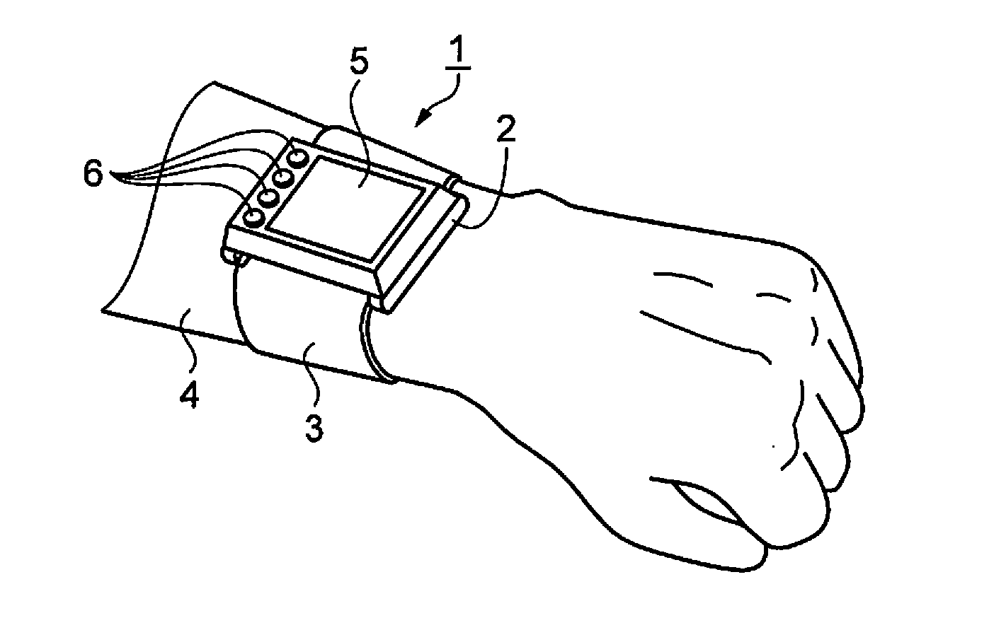
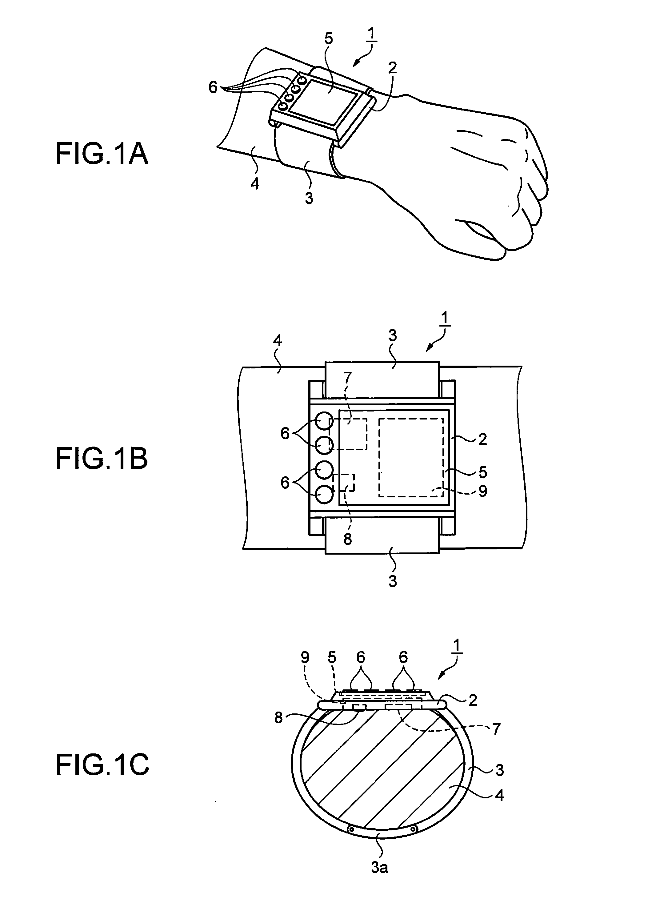
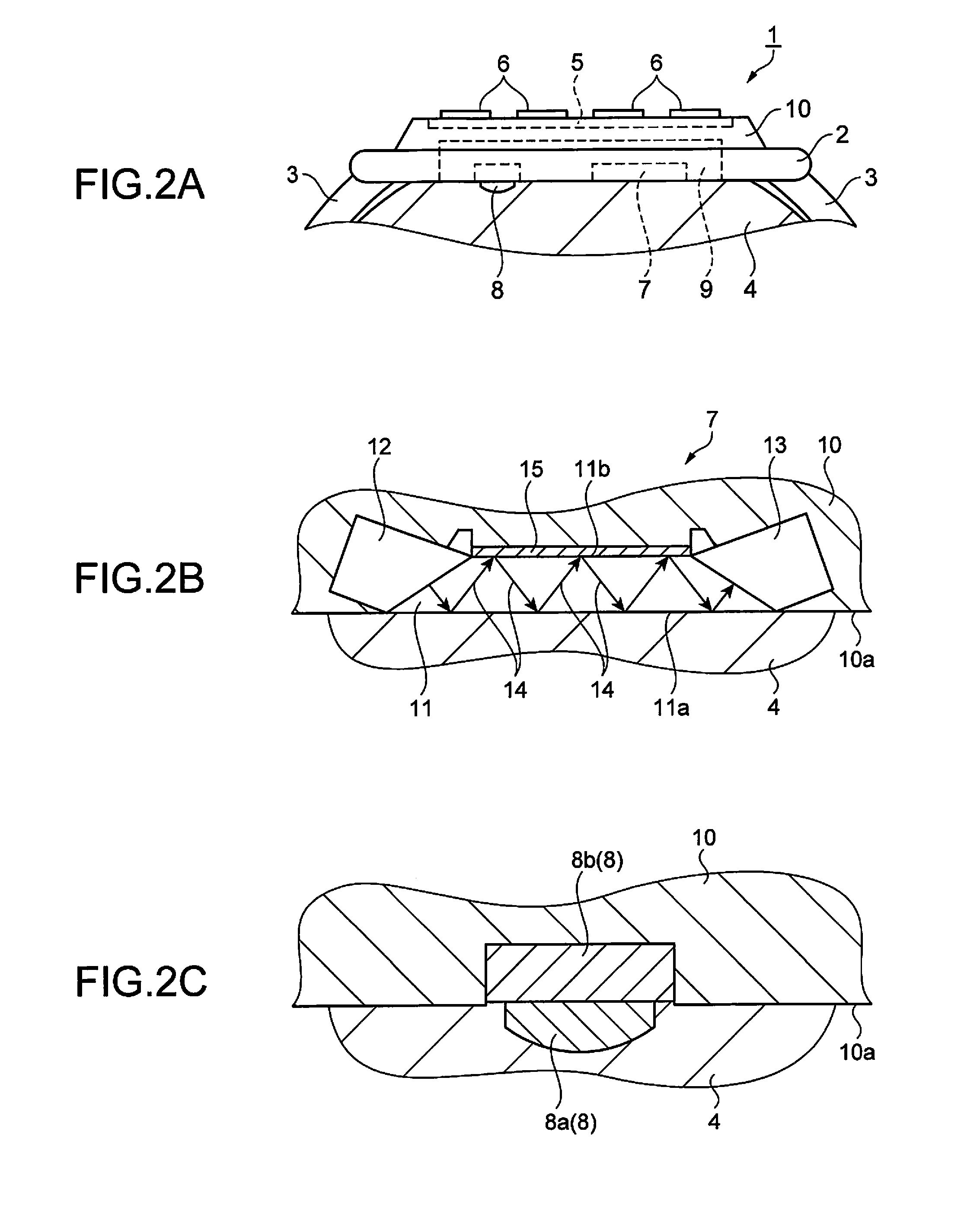
[0040]A biological measurement apparatus of a first embodiment will be described below with reference to FIGS. 1A to 3. FIG. 1A is an illustrative perspective view of the configuration of the biological measurement apparatus, and FIG. 1B is a schematic front view of the configuration of the biological measurement apparatus. FIG. 1C is a schematic side view of the configuration of the biological measurement apparatus. FIG. 2A is an enlarged schematic side view of a relevant portion of a main body unit of the biological measurement apparatus.

[0041]As shown in FIGS. 1A to 1C and FIG. 2A, a biological measurement apparatus 1 includes a main body unit 2 and a belt unit 3 provided on the main body unit 2. The main body unit 2 and the belt unit 3 form a tubular shape. An arm 4, which is a person's biological object, is inserted into the formed tube. In other words, the biological measurement apparatus 1 is used while being attached to the arm 4 like a watch.

[0042]A display apparatus 5 and ...

second embodiment

[0089]Next, another embodiment of the biological measurement apparatus will be described with reference to FIG. 7, which is an enlarged schematic view of the structure of a relevant portion of a force sensor.

[0090]This embodiment differs from the first embodiment in that a portion of the pressing protrusion 8a shown in FIG. 2C is an elastic body. Note that aspects that are the same as in the first embodiment will not be described.

[0091]In this embodiment, as shown in FIG. 7, a force sensor 46 has a sensor main body unit 46b, and a pressing protrusion 46a is provided on the arm 4 side of the sensor main body unit 46b. A piezoelectric element is built into the sensor main body unit 46b, and the piezoelectric element is sandwiched between the sensor main body unit 46b and the pressing protrusion 46a in this structure. A protrusion tip portion 46c, which is an elastic body, is provided on the arm 4 side of the pressing protrusion 46a. Pressing force that the arm 4 applies to the force s...

third embodiment

[0095]Next, another embodiment of the biological measurement apparatus will be described with reference to FIGS. 8A to 8D. FIG. 8A is an enlarged schematic view of the structure of a relevant portion of the main body unit. FIGS. 8B to 8D are schematic diagrams for describing the biological measurement method. This embodiment differs from the first embodiment in that multiple force sensors 8 are provided on the holding unit 10. Note that aspects that are the same as in the first embodiment will not be described.

[0096]In this embodiment, as shown in FIG. 8A, a biological measurement apparatus 50 includes a main body unit 51, and the infrared sensor 7 is provided at the center of the arm 4 side of the main body unit 51. Also, a first force sensor 52 and a second force sensor 53 are arranged on opposing sides of the infrared sensor 7.

[0097]FIGS. 8B, 8C, and 8D are diagrams corresponding to the pressing force detection step of step S2 and the force determination step of step S3. In FIG. ...


PUM


Abstract

A biological measurement apparatus that can measure a biological component concentration with favorable precision is provided. This apparatus includes an infrared sensor that irradiates an arm with infrared light, receives infrared light that was reflected by the arm, and outputs light intensity data; a holding unit that holds the infrared sensor such that the infrared sensor comes into contact with the arm; a force sensor that detects the force with which the infrared sensor and the arm are pressed together; a pressing force determination unit that compares the force with determination values and determines whether or not the force is in a predetermined range; and a component concentration calculation unit that calculates a component concentration of the arm using the light intensity data that was output when the pressing force determination unit determined that the force is in the predetermined range.

Description

[0001]This application claims the benefit of Japanese Patent Application No. 2014-054505, filed on Mar. 18, 2014. The content of the aforementioned application is incorporated herein by reference in its entirety.BACKGROUND[0002]1. Technical Field[0003]The present invention relates to a biological measurement apparatus and a biological measurement method.[0004]2. Related Art[0005]Review has been underway on methods for measuring the blood glucose level, blood pressure, and pulse of a person using near-infrared light and infrared light. For example, JP-A-11-188009 discloses a blood glucose level measurement apparatus that employs ATR (Attenuated Total Reflection). According to this technology, a glass plate having a reflective film provided on one surface is prepared. Then the surface of the glass plate not provided with the reflective film is brought into close contact with the skin of a biological object. Infrared light is emitted from one lateral surface of the glass plate. The inf...

Claims


Application Information

Patent Timeline
Patent Type & Authority Applications(United States)
IPC IPC(8): A61B5/1455A61B5/00A61B5/024A61B5/145A61B5/021
CPCA61B5/1455A61B5/14532A61B5/6843A61B5/02433A61B5/021A61B5/681A61B5/7221A61B2562/0247
Inventor IKEBE, TOMO
Owner SEIKO EPSON CORP
Why Eureka
Try Eureka