Pneumatic tire

a technology of pneumatic tires and tires, which is applied in the direction of vehicle components, non-skid devices, transportation and packaging, etc., can solve the problems of tire wear, tire wear, tire wear, etc., and achieve the effect of improving excellent drainage performance and on-snow performance, and large ground contact area

Active Publication Date: 2015-09-24
BRIDGESTONE CORP
View PDF2 Cites 4 Cited by
  • Summary
  • Abstract
  • Description
  • Claims
  • Application Information

AI Technical Summary

Benefits of technology

[0012]The aforementioned pneumatic tire is excellent in drainage performance and on-snow performance because the tire has a plurality of the lateral grooves continuously extending in the tire width direction between the central land portion row and each tread end. Further, since openings, interposing a lateral groove therebetween, of the first longitudinal grooves adjacent to each other in the tire circumferential direction are shifted in the tire width direction and openings, interposing a lateral groove therebetween, of the second longitudinal grooves adjacent to each other in the tire circumferential direction are shifted in the tire width direction in the tire, as described above, the tire can form snow columns in the longitudinal grooves in a satisfactory manner when it runs on a snow-covered road and thus exhibit improved on-snow performance, as compared with a tire in which the respective openings interposing a lateral groove therebetween are aligned in the tire circumferential direction. Yet further, since an end, on the one side in the tire circumferential direction, of the second intermediate block is positioned within a predetermined range as described above, timing discrepancy between a release of the first intermediate block from a road surface and a release of the second intermediate block from the road surface is shortened and separate movements of these two blocks are suppressed, whereby the first intermediate block's pulling the second intermediate block is suppressed so that the latter can ensure a satisfactorily large ground contact area when the tire is rotated. Accordingly, the tire can suppress occurrence of partial wear and improve driving performance and braking performance thereof.

Problems solved by technology

Accordingly, the second block land portion is pulled by the first block land portion and tends to be deformed and thus fail to ensure a satisfactorily large ground contact area thereof in the pneumatic tire when the tire is rotated, which possibly deteriorates driving performance and / or braking performance and causes partial wear of the tire.
Further, the pneumatic tire, in which the first block land portions have long circumferential lengths, can be provided with lateral grooves extending from the tire equatorial plane side to each tread end at only restricted positions, which results in unsatisfactory improvement in on-snow performance and drainage performance in running on a wet road surface, of the tire.

Method used


Image

  • Pneumatic tire
  • Pneumatic tire

Examples


examples

[0044]Examples of our pneumatic tire will be described hereinafter. Our pneumatic tire, however, is not restricted by these Examples by any means.

[0045]Example tires and Conventional Example tire as test tires were prepared and on-ice performances thereof were evaluated by FEM calculation.

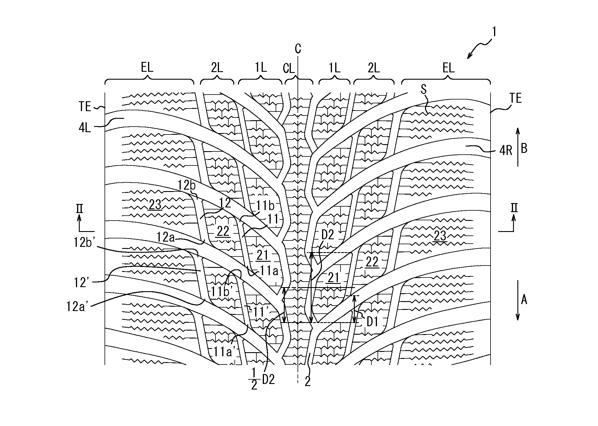
[0046]Specifically, Example 1 tire provided with a tread as shown in FIG. 1 and having D1 / D2=½, Example 2 tire provided with a tread as shown in FIG. 1 and having D1 / D2=⅙, and Conventional Example tire provided with a tread as shown in FIG. 1 and having D1 / D2=⅔ were first prepared. Then, a ground contact area on a virtual road surface was measured for each of the Example tires and the Conventional Example tire by FEM calculations. The results are expressed by index values relative to the result (the ground contact area) of Comparative Example being “100” in Table 1. The larger index value represents the better performance in Table 1.

TABLE 1Example 1Example 2Conventional ExampleD1 / D21 / 21 / 62 / 3Ground ...


PUM


Abstract

A pneumatic tire, having in a tread surface thereof a pair of circumferential grooves formed on respective sides of the tire equatorial plane in the middle, a rib-like central land portion row demarcated by the circumferential grooves, and a plurality of lateral grooves extending between the central land portion row and each tread end, comprises in each half region of the tread: a row of first intermediate blocks each having a circumferential length D2 and demarcated by the lateral grooves, the corresponding circumferential groove, and first longitudinal grooves; and a row of second intermediate blocks demarcated by the lateral grooves, the first longitudinal grooves, and second longitudinal grooves, wherein facing openings of the first/second longitudinal grooves adjacent in the tire circumferential direction are offset from each other, and provided that D1 represents a circumferential distance between adjacent ends of the adjacent first and second intermediate blocks, D1≦D2/2.

Description

TECHNICAL FIELD[0001]The present invention relates to a pneumatic tire and in particular a pneumatic tire suitably used as a winter tire.BACKGROUND ART[0002]There has conventionally been proposed as a pneumatic tire for use on a snow-covered / frozen road a pneumatic tire having: a rib-like land portion situated on the tire equatorial plane; and three pairs of block land portion rows provided such that rows of block land portions of each pair are disposed on respective sides of the tire equatorial plane, wherein a large number of sipes are formed in the rib-like land portion and the block land portions (refer to PTL 1, for example).CITATION LISTPatent Literature[0003]PTL 1: JP4397956SUMMARY[0004]In the pneumatic tire disclosed in PTL 1, however, timing for edge portions of a first block land portion to be released from a ground surface differs from timing for edge portions of a second block land portion to be released from the ground surface when the tire is rotated, although the firs...

Claims


Application Information

Patent Timeline
Patent Type & Authority Applications(United States)
IPC IPC(8): B60C11/03
CPCB60C11/0304B60C2011/0358B60C2011/0353B60C2011/0346B60C11/0302B60C11/0306B60C2011/0351B60C2011/0374B60C2011/0388B60C2011/1213B60C2011/1227B60C2011/1245
Inventor TAKEI, ATAKA
Owner BRIDGESTONE CORP
Why Eureka
Try Eureka