Method and a device for issuing terrain avoidance warnings for a rotary wing aircraft

a technology terrain avoidance, which is applied in the direction of actuating personally, process and machine control, instruments, etc., can solve the problems of difficult to implement such a function, not well adapted or suitable for rotary wing aircraft, etc., and achieves the effect of increasing the vertical speed of the aircraft, increasing the mechanical power, and not putting additional strain on the engin

Active Publication Date: 2015-09-24
EUROCOPTER
View PDF9 Cites 11 Cited by
  • Summary
  • Abstract
  • Description
  • Claims
  • Application Information

AI Technical Summary

Benefits of technology

[0080]The deceleration stage is performed in particular with the help of a cyclic stick of the rotary wing aircraft, the cyclic stick controlling the cyclic pitch of the blades of the main rotor of the aircraft. Action on the cyclic stick enables the aircraft to take a nose-up attitude, thereby slowing it down and transforming a portion of its kinetic energy into potential energy. This deceleration stage thus makes it possible initially to gain altitude “for free” without putting additional strain on the engines and to increase the vertical speed of the aircraft.
[0081]Furthermore, and advantageously, the predetermined avoidance maneuver is based on the pilot acting on a collective stick of the aircraft as from the deceleration stage in order to increase the collective pitch of the blades of the main rotor of the rotary wing aircraft, unlike conventional deceleration maneuvers in level flight in which the collective pitch needs to be reduced. As a result, by pulling on the collective stick while also making use of a first limit indicator (FLI) the pilot can monitor the power developed by the engines of the aircraft. Thus, the pilot can control the power developed by the engines of the aircraft so that it is set on a value that is substantially equal to the predetermined maximum power, thereby having a large amount of power available without running the risk of damaging the engines.
[0082]The pilot preferably acts simultaneously on the cyclic stick and on the collective stick so as to cause the aircraft both to take on a nose-up attitude and to increase the mechanical power developed by the drive train of the aircraft. The aircraft can thus reach the predetermined forward speed Vafinal while keeping the power of its engines at the predetermined maximum power, thereby maximizing the rate of climb of the aircraft.

Problems solved by technology

These systems have been designed mainly for airplanes and they are not well adapted or suitable for rotary wing aircraft.
During such flights, the parameters taken into consideration and the warnings supplied by a terrain avoidance system designed for an airplane are not appropriate and are possibly even undesirable for rotary wing aircraft, since they might constitute a nuisance for the pilot.
In addition, since the controls for piloting a rotary wing aircraft are fundamentally different from those of an airplane, executing an avoidance maneuver requires specific piloting actions to be taken that are different from those in an airplane.
Nevertheless, it can be understood that the variety of possible trajectories that can be performed by a rotary wing aircraft close to the relief and the obstacles makes it difficult to implement such a function of issuing a warning to enable an aircraft of this type to avoid the terrain.
Nevertheless, a definition of the avoidance trajectory that is too approximate may give rise to warnings being issued that are untimely and inappropriate, thereby encouraging the pilot to deactivate the system instead of having confidence in it and making using of it.

Method used


Image

  • Method and a device for issuing terrain avoidance warnings for a rotary wing aircraft
  • Method and a device for issuing terrain avoidance warnings for a rotary wing aircraft
  • Method and a device for issuing terrain avoidance warnings for a rotary wing aircraft

Examples


Embodiment Construction

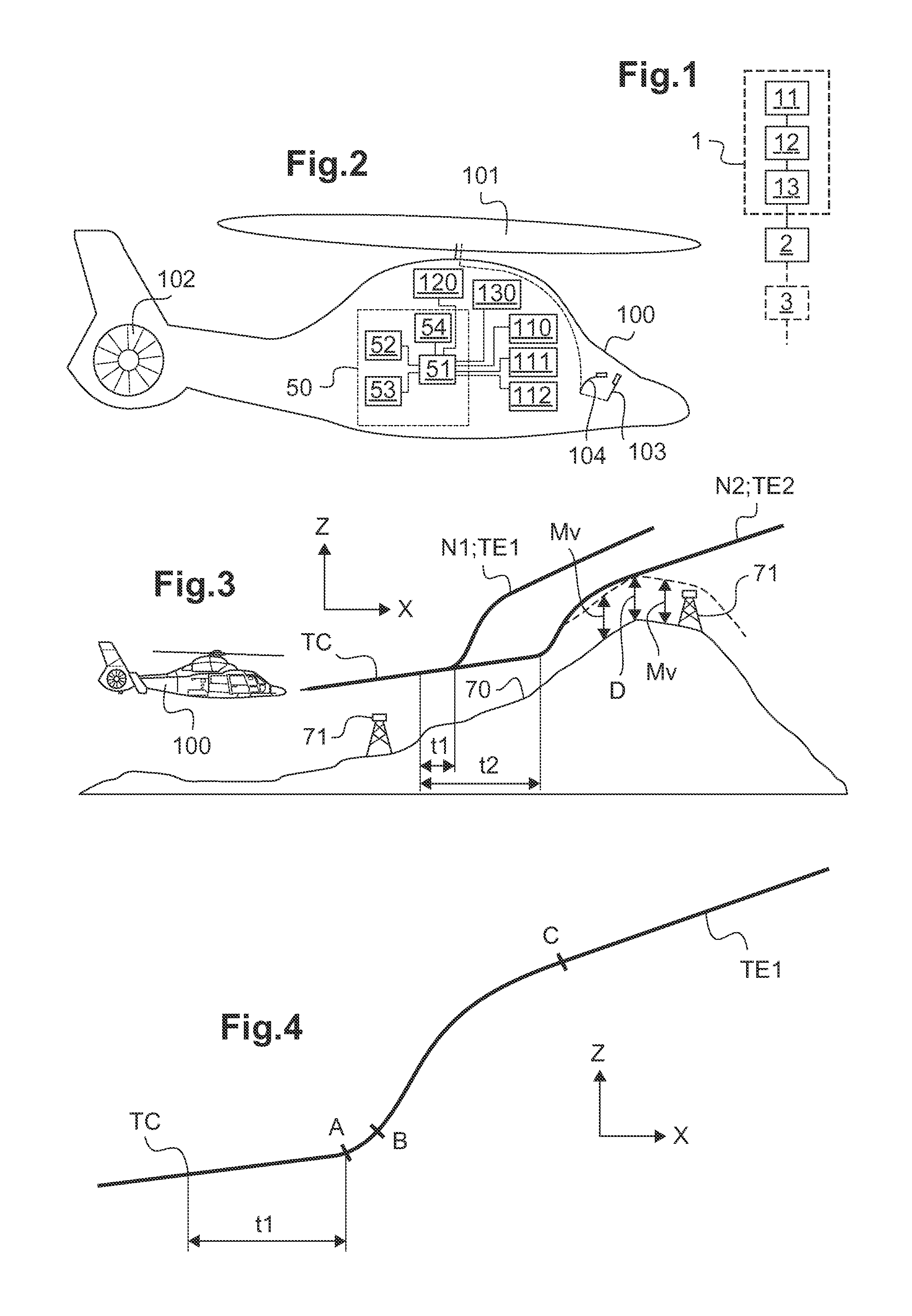
[0130]Elements present in more than one of the figures are given the same references in each of them.

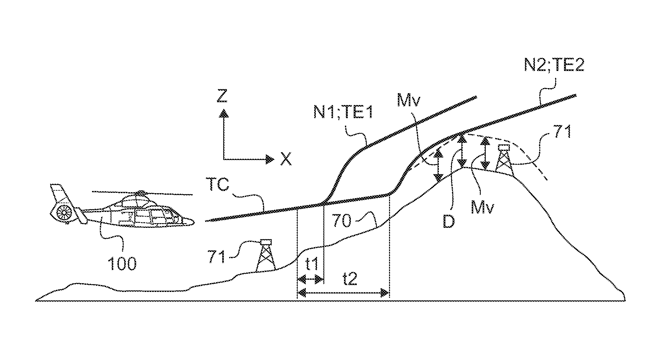
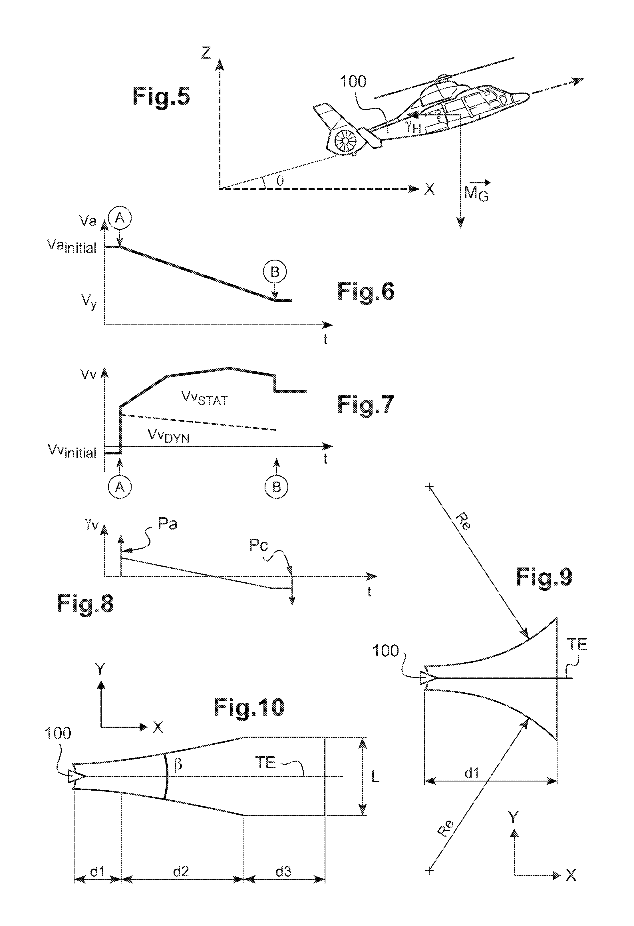
[0131]The figures show three directions X, Y, and Z that are mutually orthogonal and that form an orthogonal reference frame X, Y, Z.

[0132]A direction X is said to be “longitudinal”, and corresponds to lengths or main dimensions of the structures described. Thus, the longitudinal direction X defines the main forward axis of the aircraft described and the tangents to their instantaneous trajectories at their centers of gravity.

[0133]Another direction Y is said to be “transverse”, and corresponds to lateral trajectories or coordinates of the structures described. For simplification purposes, these longitudinal and transverse directions X and Y are sometimes said to be “horizontal”, forming a horizontal XY plane.

[0134]A third direction Z is said to be “in elevation” and corresponds to height and altitude dimensions of the structures described. For simplification purposes, this direction...


PUM


Abstract

A method and a device (50) for issuing a terrain avoidance warning for a rotary wing aircraft (100) during which at least one bundle (N1, N2) of possible avoidance trajectories for said aircraft (100) is prepared in order to avoid a collision between said aircraft (100) and the relief (70) being overflown. A warning is then triggered as soon as said relief (70) being overflown is found to be at a distance from any one of said bundles (N1, N2) of possible avoidance trajectories that is less than a predetermined distance (Mv). Said avoidance trajectories are determined on the basis of a predetermined avoidance maneuver and on the basis of states of said aircraft (100), said predetermined avoidance maneuver being performed at a predetermined maximum power of said aircraft (100).

Description

CROSS REFERENCE TO RELATED APPLICATION[0001]This application claims priority to French patent application No. FR 13 01635 filed on Jul. 10, 2013, the disclosure of which is incorporated in its entirety by reference herein.BACKGROUND OF THE INVENTION[0002](1) Field of the Invention[0003]The present invention relates to the general technical field of providing assistance in piloting rotary wing aircraft, and in particular to the fields of obstacle avoidance warnings. More particularly, the present invention relates to a method of issuing a warning to enable a rotary wing aircraft to avoid terrain, and it also relates to a device for performing the method and to an aircraft including such a device.[0004](2) Description of Related Art[0005]Such piloting assistance systems for issuing a terrain avoidance warning are known as terrain avoidance warning systems (TAWS).[0006]While dangerous obstacles and relief situated ahead of the trajectory of an aircraft are being approached, a TAWS serv...

Claims


Application Information

Patent Timeline
Patent Type & Authority Applications(United States)
IPC IPC(8): B64D45/04B64C27/56B64C27/57
CPCB64D45/04B64C27/56B64C27/57G08G5/0086G08G5/045
Inventor PETILLON, JEAN-PAUL
Owner EUROCOPTER
Why Eureka
Try Eureka