Overlock sewing machine

a sewing machine and overlock technology, applied in the field of overlock sewing machines, can solve the problems of unfavorable operating feelings, direct catch of load changes by users, and unfavorable operation effects of operation, and achieve the effect of easy determination and favorable operating feelings

Active Publication Date: 2015-09-24
JANOME CORP
View PDF7 Cites 7 Cited by
  • Summary
  • Abstract
  • Description
  • Claims
  • Application Information

AI Technical Summary

Benefits of technology

[0016]One or more embodiments of the present invention provides an overlock sewing machine in which looper threading operations to loopers can be performed with one hand with favorable operation feelings and in which it is easy to determine whether it is in a sewing enabled state or not.
[0020]According to one or more embodiments of the present invention, it is possible to perform looper threading operations to the loopers by one hand with favorable operating feelings and it is also possible to easily determine whether it is in a sewing executable state or not.

Problems solved by technology

However, in the device of Patent Document 3, a user needs to operate a member including the groove cam in a sliding manner, which lead to negative impression of operability.
More particularly, in the device of Patent Document 3, large load changes are caused when the control pin runs onto a plurality of cam positions, and these load changes are directly caught by the user.
Particularly for users who operate this device for the first time, there were cases in which they felt uneasy whether they should proceed with further operations since sliding of the operating member felt suddenly heavier.

Method used


Image

  • Overlock sewing machine
  • Overlock sewing machine
  • Overlock sewing machine

Examples


first embodiment

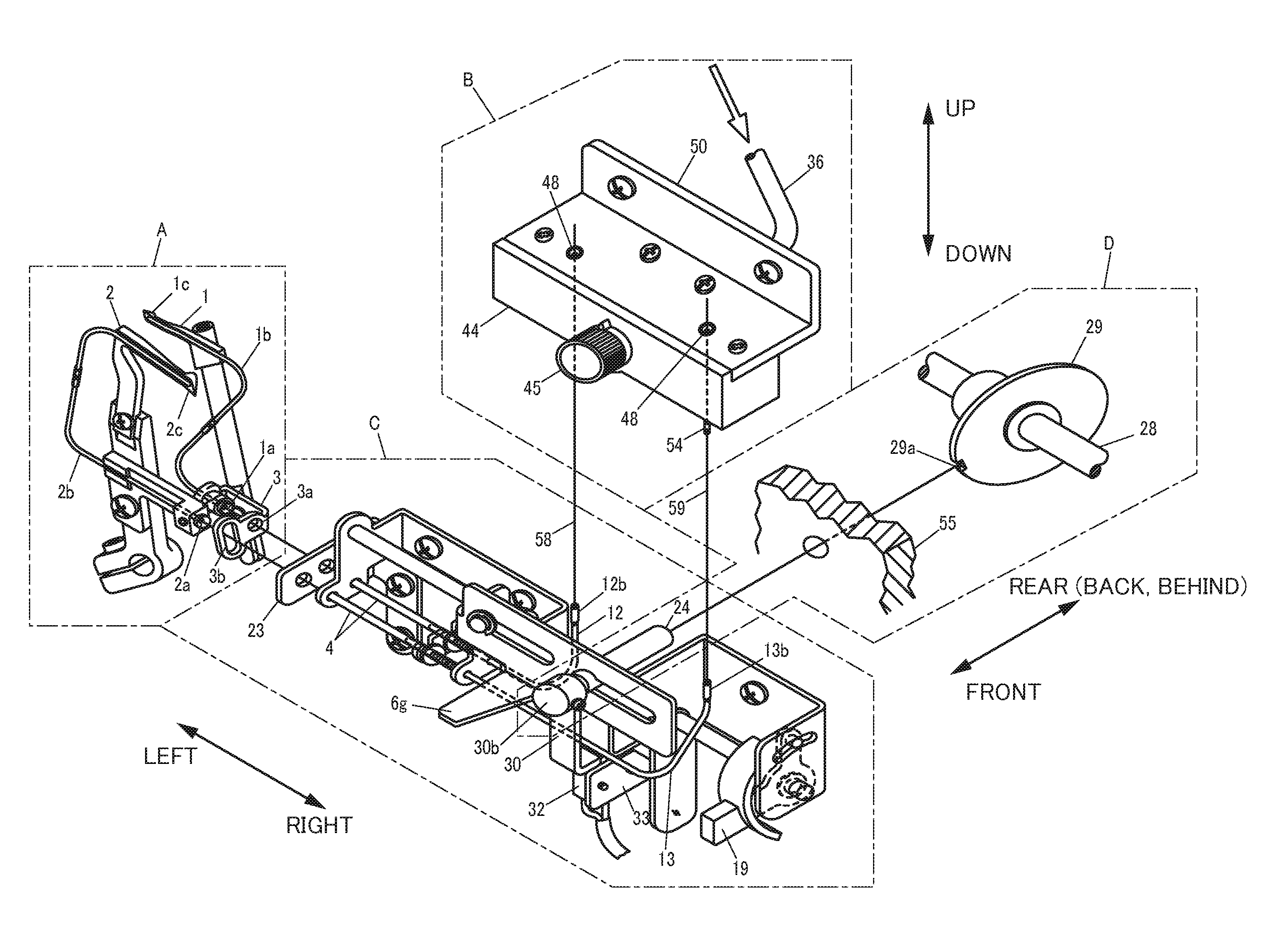
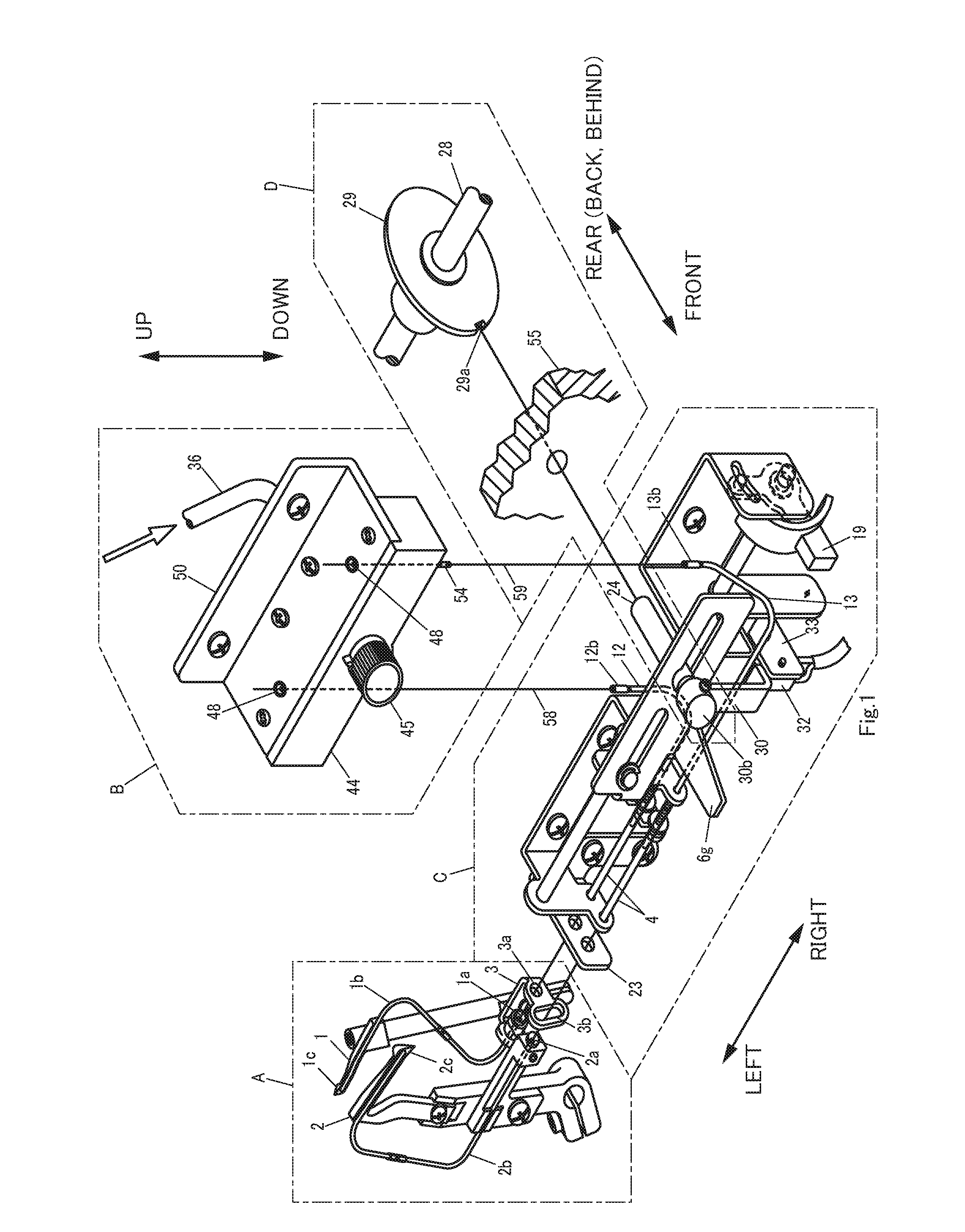
[0049]FIG. 1 is a perspective view of main portions for showing an embodiment of an overlock sewing machine according to the present invention.

[0050]In this respect, each of the drawings including FIG. 1 indicated hereinafter are schematically illustrated drawings and sizes and shapes of respective portions are shown in suitably exaggerated form for ease of understanding.

[0051]Further, while explanations are made upon indicating specific numerical values, shapes and materials in the following explanations, they may be suitably changed.

[0052]Moreover, for ease of understanding and for convenience sake, explanations will be made by suitably using the six directions of front (or near), rear (or back, behind), left, right, up and down as indicated by arrows in FIG. 1. However, these directions are not to limit the arrangement of the invention.

[0053]In the present embodiment, explanations will be made by giving a case of an overlock sewing machine comprising two loopers (upper looper 1, ...

modified embodiment

[0147]The present invention is not limited to the above explained embodiment but various modifications and changes are possible which are also included in the present invention.

[0148](1) In the present embodiment, the relationship between the main shaft fixing outer shaft 24 as the first shaft and the main shaft fixing inner shaft 26 as the second shaft has been explained while citing an example in which the second shaft side is located inside. The present invention is not limited to this arrangement, and it can be arranged in that the first shaft side is inside and the second shaft side is outside. Further, the invention is not limited to an embodiment in which one shaft is inserted into the interior of the other shaft, but any arrangement in which both members are relatively movable in an axial direction would do, and any embodiment including, for instance, a case in which a rail-like guide portion is provided, would do.

[0149](2) In the present embodiment, explanations have been m...


PUM


Abstract

An overlock sewing machine includes a main shaft fixing operating arm provided with a shaft pin engaging portion that engages with a fixing inner shaft pin and an arm provided to be operable by a user which are integrally rockable within a specified range, and further includes a main shaft fixing operating spring which urging direction is switched in both directions of an rocking direction by exceeding a neutral point by the rocking movements of the main shaft operating arm and the arm.

Description

CROSS REFERENCE TO RELATED APPLICATIONS[0001]This application is based on and claims the benefit of priority to Japanese Patent Application No. 2014-055392 filed on Mar. 18, 2014, the contents of which are hereby incorporated by reference in their entirety.TECHNICAL FIELD[0002]The present invention relates to an overlock sewing machine in which looper threads can be threaded to loopers utilizing power of air.BACKGROUND ART[0003]An overlock sewing machine is provided with a plurality of loopers, and since it is necessary to thread each of the loopers with respectively different looper threads, threading operations were troublesome.[0004]Patent Document 1 discloses a device for threading a thread to a hollow looper point using compressed air.[0005]Patent Document 2 discloses a compressed air path switching device corresponding to a plurality of loopers.[0006]These techniques have enabled easy threading operations of looper threads to loopers.[0007]On the one hand, the devices disclose...

Claims


Application Information

Patent Timeline
Patent Type & Authority Applications(United States)
IPC IPC(8): D05B87/00D05B57/34
CPCD05B87/00D05B57/34D05B87/02D05B63/00B65H57/12D05D2207/04
Inventor SHOMURA, EIICHI
Owner JANOME CORP
Why Eureka
Try Eureka