Physical quantity sensor, altimeter, electronic apparatus, and moving object
a technology of physical quantity sensor and altimeter, which is applied in the direction of fluid pressure measurement by mechanical elements, instruments, measurement devices, etc., can solve the problems of inability to provide excellent pressure detection accuracy, the piezoresistive elements included in the pressure detecting bridge circuit cannot be disposed in proximity of the piezoresistive elements included and the inability to accurately sense the temperature in the temperature sensing bridge circuit. achieve the effect of high reliability
- Summary
- Abstract
- Description
- Claims
- Application Information
AI Technical Summary
Benefits of technology
Problems solved by technology
Method used
Image
Examples
first embodiment
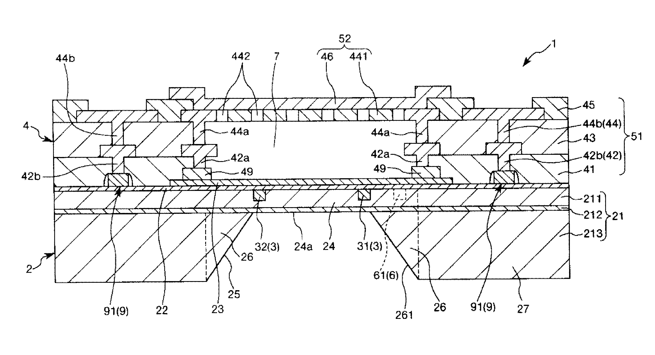
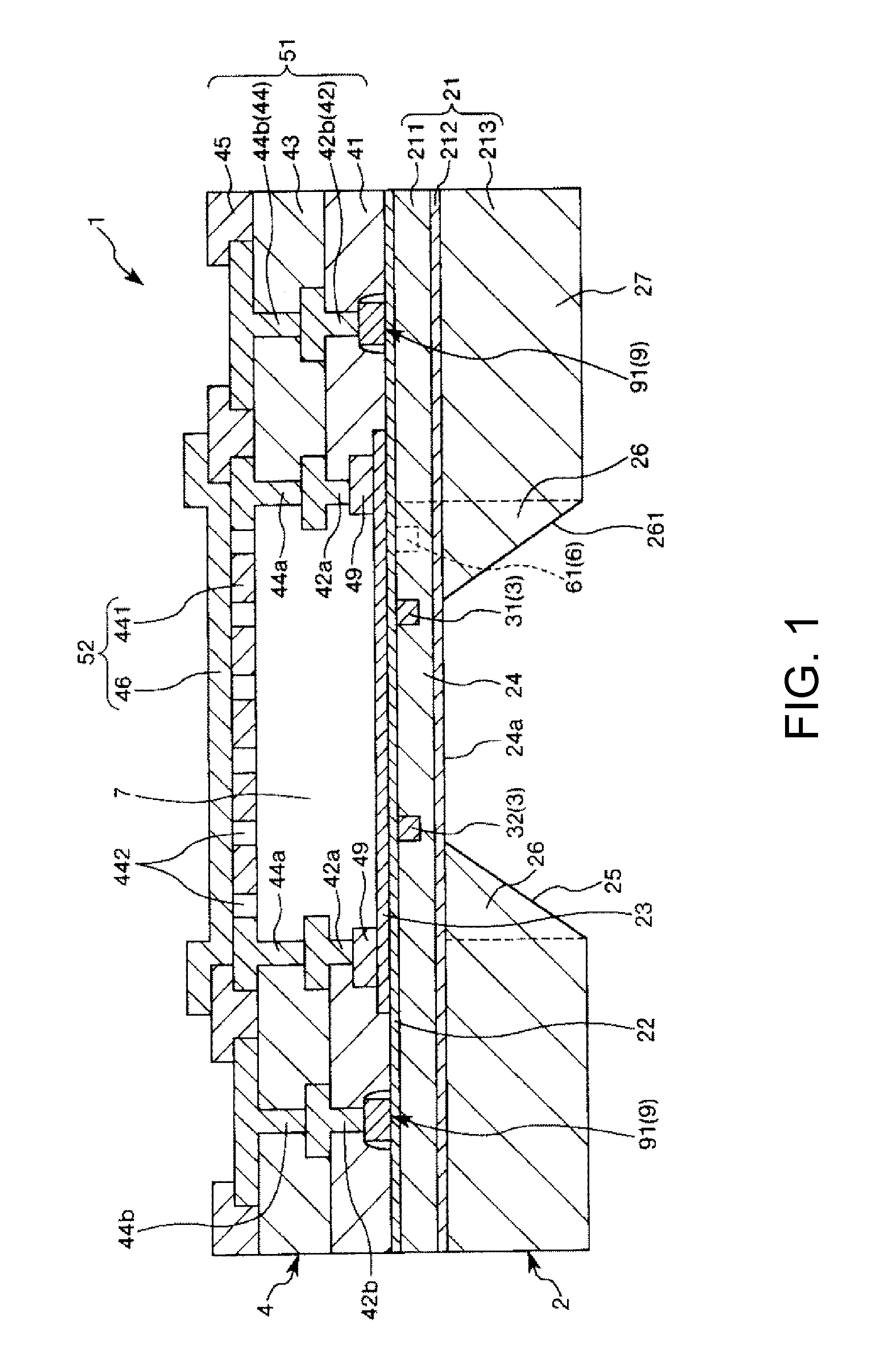
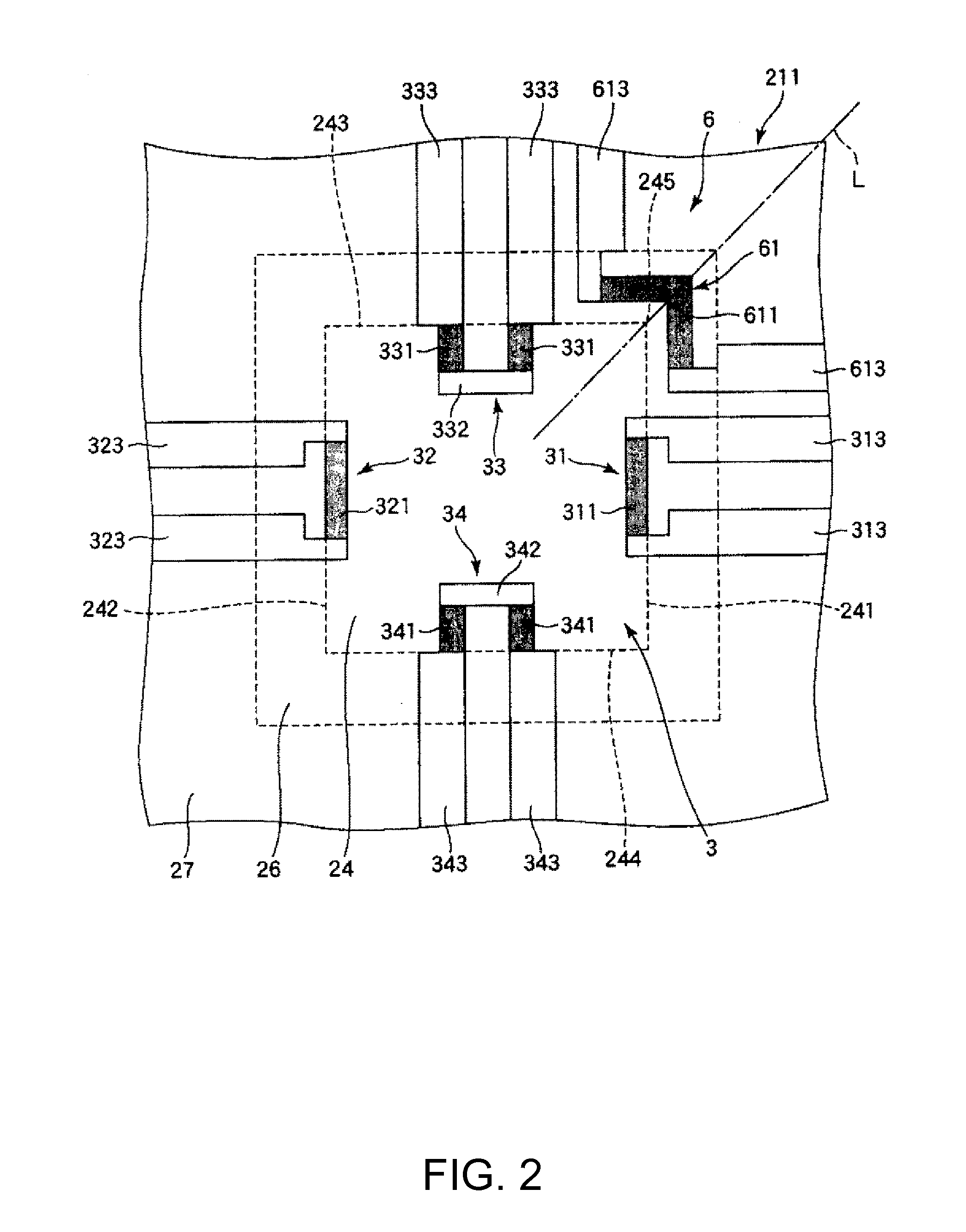
[0057]FIG. 1 is a cross-sectional view showing a first embodiment of a physical quantity sensor according to the invention. FIG. 2 is a plan view showing a deflection amount sensor and a temperature sensor that are included in the physical quantity sensor shown in FIG. 1. FIG. 3 is a diagram for explaining a circuit including the deflection amount sensor shown in FIG. 2. FIGS. 4 to 11 are cross-sectional views for explaining a method for manufacturing the physical quantity sensor shown in FIG. 1. In the following description, the upper side in FIG. 1 is defined as “up”, and the lower side is defined as “down”.
[0058]The physical quantity sensor 1 is a pressure sensor that can detect pressure. With the use of the physical quantity sensor 1 as a pressure sensor, the physical quantity sensor 1 can be mounted on various electronic apparatuses for purposes of, for example, measuring altitude.
[0059]As shown in FIG. 1, the physical quantity sensor 1 includes a substrate 2, the deflection am...
second embodiment
[0105]Next, a second embodiment of a physical quantity sensor according to the invention will be described.
[0106]FIG. 12 is a plan view showing the second embodiment of the physical quantity sensor according to the invention. FIG. 13 is a diagram for explaining a circuit including a temperature sensor shown in FIG. 12.
[0107]Hereinafter, the second embodiment of the physical quantity sensor according to the invention will be described, in which differences from the embodiment described above are mainly described and the description of similar matters is omitted.
[0108]The second embodiment is similar to the first embodiment described above, except that the configuration of the temperature sensor is different.
[0109]As shown in FIG. 12, a temperature sensor 6 of the embodiment includes four piezoresistive elements (temperature sensing elements) 61, 62, 63, and 64. The piezoresistive elements 61, 62, 63, and 64 include piezoresistive portions 611, 621, 631, and 641. Wires 613, 623, 633, ...
third embodiment
[0115]Next, a third embodiment of a physical quantity sensor according to the invention will be described.
[0116]FIG. 14 is a cross-sectional view showing the third embodiment of the physical quantity sensor according to the invention.
[0117]Hereinafter, the third embodiment of the physical quantity sensor according to the invention will be described, in which differences from the embodiments described above are mainly described and the description of similar matters is omitted.
[0118]The third embodiment is similar to the first embodiment described above, except that the arrangement of the temperature sensor is different.
[0119]As shown in FIG. 14, in the physical quantity sensor of the embodiment, the piezoresistive element 61 (the piezoresistive portion 611) included in the temperature sensor 6 is located outside the cavity portion 7 in the plan view. That is, in the plan view, the diaphragm 24 and the cavity portion 7 overlap each other, while the piezoresistive element 61 and the c...
PUM
 Abstract
Description
Claims
Application Information
 - R&D
- Intellectual Property
- Life Sciences
- Materials
- Tech Scout
- Unparalleled Data Quality
- Higher Quality Content
- 60% Fewer Hallucinations
Browse by: Latest US Patents, China's latest patents, Technical Efficacy Thesaurus, Application Domain, Technology Topic, Popular Technical Reports.
© 2025 PatSnap. All rights reserved.Legal|Privacy policy|Modern Slavery Act Transparency Statement|Sitemap|About US| Contact US: help@patsnap.com


