High temperature, zero fiber strain, fiber optic cable

a fiber optic cable, high temperature technology, applied in the direction of optics, fibre mechanical structures, instruments, etc., can solve the problems of affecting the optical performance of the cable, the upper temperature is still limited to a maximum of 150 degrees c, and the design is problemati

Active Publication Date: 2015-09-24
AFL COMM LLC
View PDF24 Cites 9 Cited by
  • Summary
  • Abstract
  • Description
  • Claims
  • Application Information

AI Technical Summary

Problems solved by technology

These designs have been problematic in the field for several of reasons.
Hydrogen evolution is detrimental to the optical performance of the cable.
Another issue is the upper temperature is still limited to a maximum of 150 degrees C. Though there are some polymers that are capable of going to higher temps, such as 300 degrees C., none can go to 600 C or even higher.
There are various methods defined in prior art for accomplishing this installation however all of them require equipment and processes that add complexity, ris

Method used


Image

  • High temperature, zero fiber strain, fiber optic cable
  • High temperature, zero fiber strain, fiber optic cable
  • High temperature, zero fiber strain, fiber optic cable

Examples


Embodiment Construction

[0024]The following detailed description is provided to gain a comprehensive understanding of the methods, apparatuses and / or systems described herein. Various changes, modifications, and equivalents of the systems, apparatuses and / or methods described herein will suggest themselves to those of ordinary skill in the art. Descriptions of well-known functions and structures are omitted to enhance clarity and conciseness.

[0025]Hereinafter, an exemplary embodiment will be described with reference to accompanying drawings.

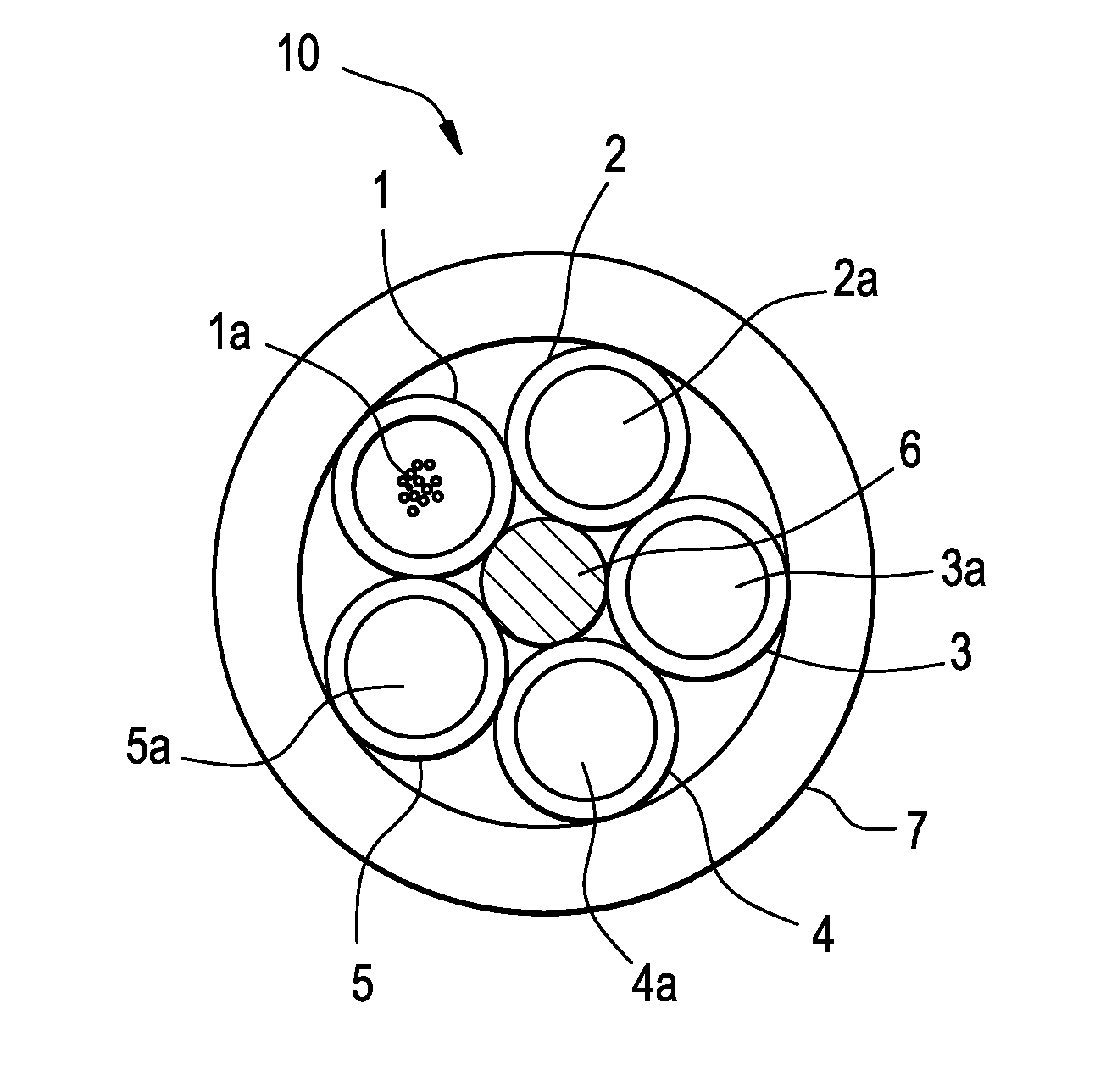
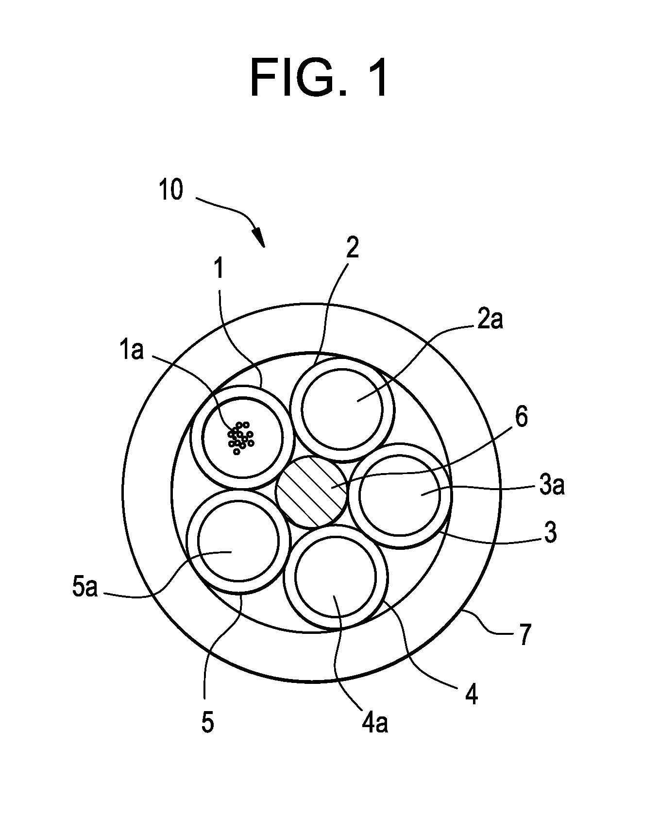
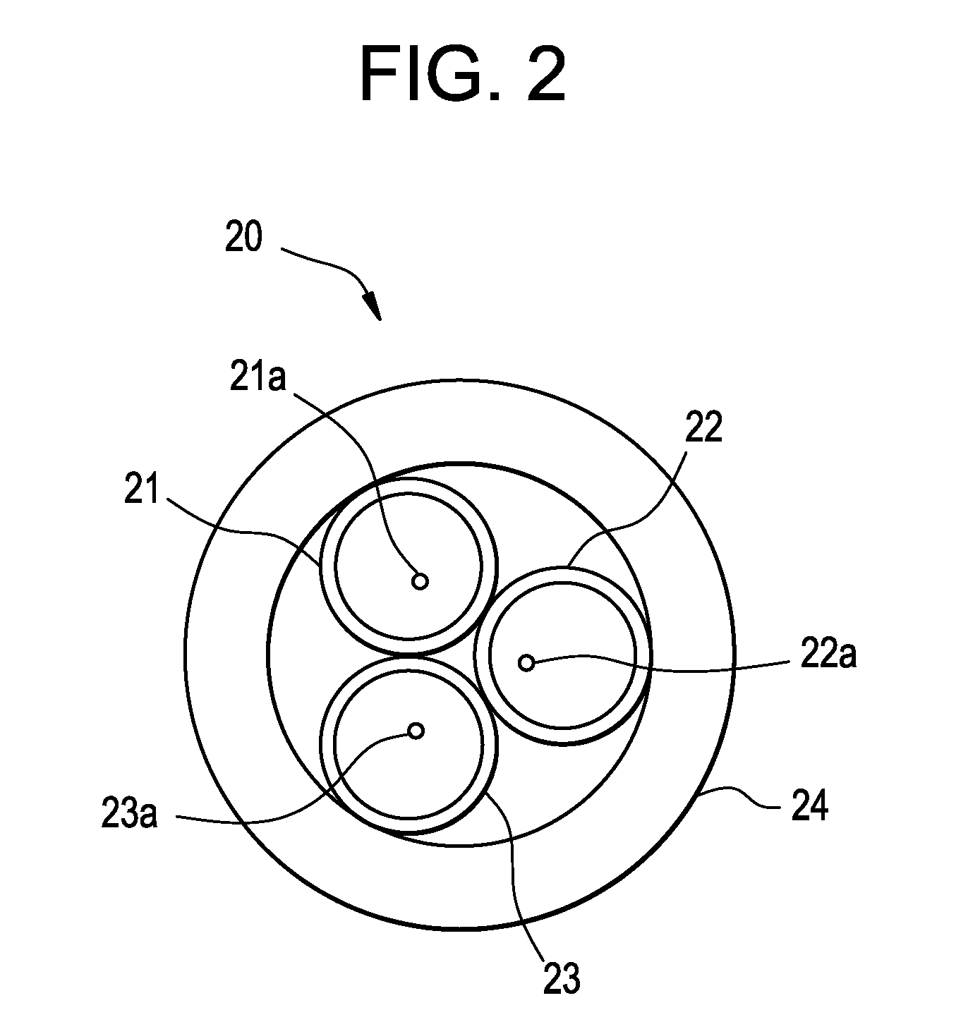
[0026]The invention provides an internal core structure that enhances the fatigue life of the cable and reduces the risk of the cable falling into the wellbore. Due to the helically stranded nature of the core, each element in the core will undergo less bend strain than that of the outer tube during deployment and retrieval over standard sheaves and bullwheels. This means the fatigue life of the core will exceed the fatigue life of the tube such that if the outer tube u...


PUM


Abstract

A cable including an outer metal tube and a first layer wire inside the outer metal tube, wherein the first layer wire has five inner elements surrounding a metallic center member and at least one of the inner elements is a metal tube containing an optical fiber.

Description

CROSS-REFERENCE TO RELATED APPLICATIONS[0001]This application is based upon and claims the benefit of priority from U.S. Provisional Application No. 61 / 614,870, filed Mar. 23, 2012, in the United States Patent and Trademark Office, the disclosures of which are incorporated herein in its entirety by reference.BACKGROUND[0002]1. Field[0003]The invention is related to a fiber optic cable, and more particularly to a high temperature zero fiber strain fiber optic cable that can be deployed in oil and gas well applications.[0004]2. Related Art and Background[0005]There is a need for high temperature, zero fiber strain, fiber optic cables that can be deployed in high temperature environments, such as oil and gas wells. These cables may be deployed directly in the wells as opposed to in a coiled tube that is then deployed in the well.[0006]Some conventional cables use stranded tubes where the tubes are made with ETFE (Teflon). These designs have been problematic in the field for several of ...

Claims


Application Information

Patent Timeline
IPC IPC(8): G02B6/44
CPCG02B6/4436G02B6/4433G02B6/4434G02B6/4416G02B6/4413G02B6/4427G02B6/443G02B6/44382
Inventor STRATTON, CRAIGPAYNE, DAVID
Owner AFL COMM LLC
Why Eureka
Try Eureka