Barrel assembly for a rivet gun

a rivet gun and barrel assembly technology, applied in metal-working equipment, metal-working equipment, manufacturing tools, etc., can solve the problem of meaningless consumption of high-pressure air, and achieve the effect of reducing high-pressure air consumption

Inactive Publication Date: 2015-10-01
LIN YU TANG
View PDF10 Cites 7 Cited by
  • Summary
  • Abstract
  • Description
  • Claims
  • Application Information

AI Technical Summary

Benefits of technology

[0010]The main objective of the invention is to provide a barrel assembly for a rivet gun that prevents pneumatic cylinder from outputting high pressure air after an operation of pulling a rivet is completed, which reduces high pressure air consumption.

Problems solved by technology

However, after the vise assembly completes the action of pulling the rivet and stays at a back position, the pneumatic cylinder continues outputting high pressure air through the bypass hole to external atmosphere, which meaninglessly consumes the high pressure air.

Method used


Image

  • Barrel assembly for a rivet gun
  • Barrel assembly for a rivet gun
  • Barrel assembly for a rivet gun

Examples


Embodiment Construction

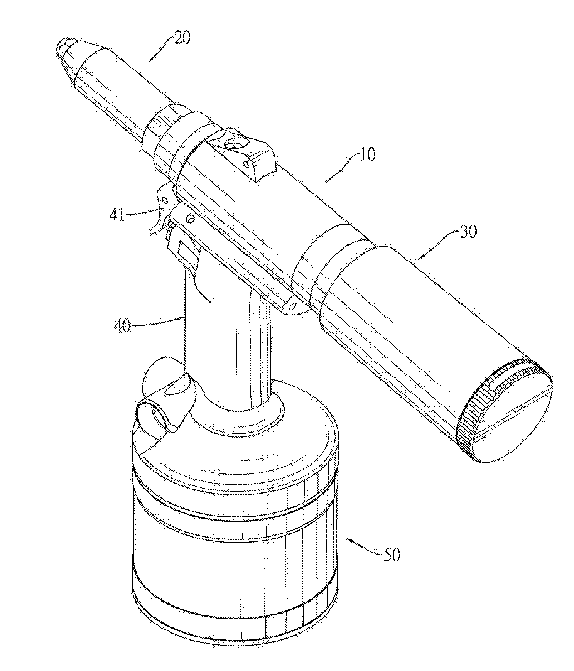
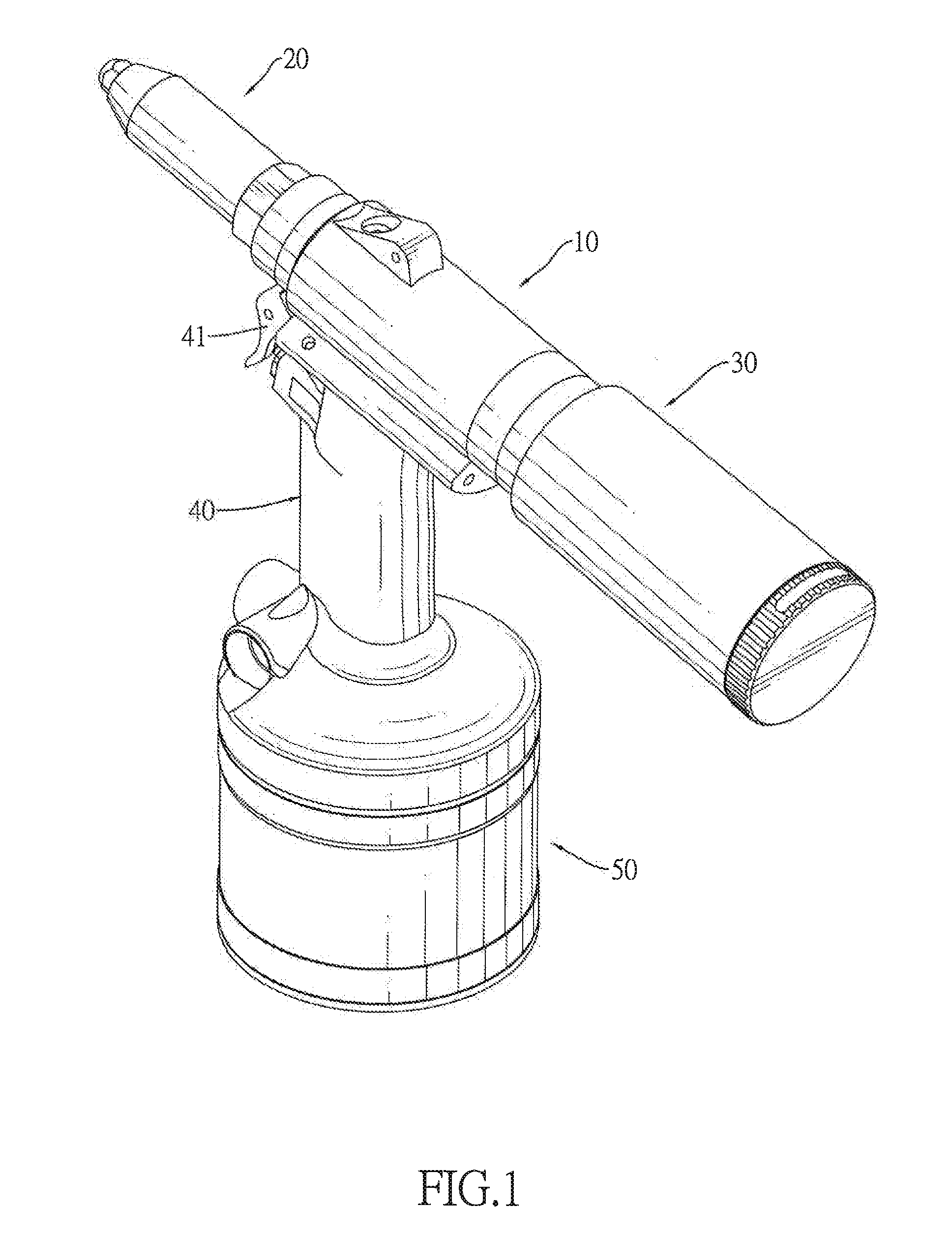
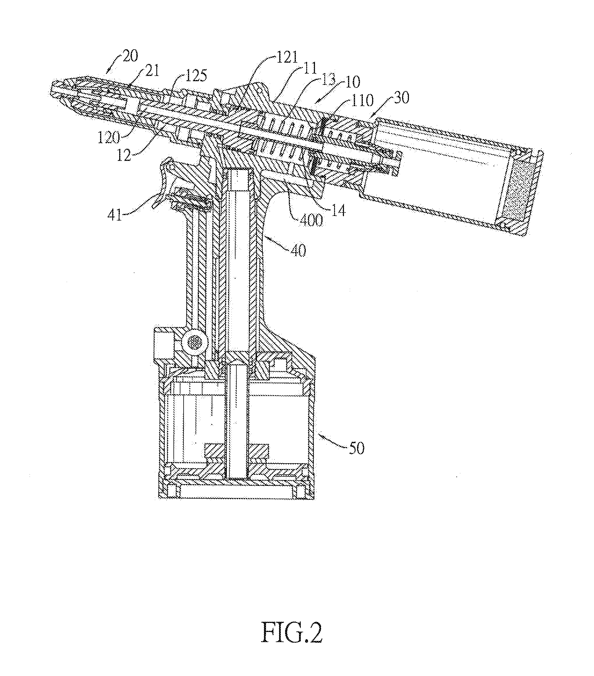
[0021]With reference to FIGS. 1 and 2, a barrel assembly 10 in accordance with the present invention may be assembled with a handle 40 and a pneumatic cylinder 50 into a complete rivet gun. The handle 40 has a mounting slot 400 and trigger 41 for driving the rivet gun to pull a rivet. The pneumatic cylinder 50 may be connected to a high pressure source to output high pressure air into the barrel assembly 10.

[0022]With further reference FIGS. 3 to 6, the barrel assembly 10 may be mounted on the mounting slot 400 of the handle 40 and comprises a tube body 11, a vising piston 12, a spring 13, a connecting tube 14 and may further have a tool head 20 and a rear valve 30.

[0023]With further reference to FIGS. 7 and 8, the tube body 11 has an assembling hole 110, a bypass hole 111 and a sleeve 15. The assembling hole 110 is defined longitudinally through the tube body 11 and has a front opening 1101 and a rear opening 1102. The bypass hole 111 is defined transversely through the tube body 1...


PUM

PropertyMeasurementUnit
pressureaaaaaaaaaa
pressuresaaaaaaaaaa
resetting forceaaaaaaaaaa

Abstract

A barrel assembly for a rivet gun has a tube body, a vising piston and a rear valve. The tube body has an assembling hole and a bypass hole. The vising piston is mounted slidably in the assembling hole of the tube body and has a piston head mounted slidably in the assembling hole of the tube body and having two O-rings mounted around the piston head at an interval, and a shaft formed on the piston head. The rear valve mounted on the rear opening of the assembling hole of the tube body. When the vi sing piston moves backward adjacent to the rear opening of the assembling hole of the tube body, the bypass hole of the tube body is located at the interval between the O-rings and is sealed by the 0-rings without consuming high pressure air from a pneumatic cylinder.

Description

BACKGROUND OF THE INVENTION[0001]1. Field of the Invention[0002]The present invention relates to a barrel assembly, and more particularly to a barrel assembly for a rivet gun that prevents pneumatic cylinder from outputting high pressure air after an operation of pulling a rivet is completed, which reduces high pressure air consumption.[0003]2. Description of Related Art[0004]A conventional rivet gun is used to rivet two boards such that the boards are securely mounted together by rivets. A rivet has a cap and a core pin. The cap is T-shaped and has an enlarged end and a mounting end. The core pin is mounted longitudinally through and protrudes out of the cap and has two ends and a ball formed on one end and adjacent to the mounting end of the cap.[0005]A conventional rivet gun comprises a barrel, a handle, a trigger, a pin collector and a pneumatic cylinder.[0006]The barrel has a front end, a rear end and a vise assembly that may vise and pull a core pin of a rivet on the front end...

Claims


Application Information

Patent Timeline
Patent Type & Authority Applications(United States)
IPC IPC(8): B21J15/30B21J15/10
CPCB21J15/105B21J15/30B21J15/043B21J15/22Y10T29/53774
Inventor LIN, YU-TANG
Owner LIN YU TANG
Why Eureka
Try Eureka