Bonding member
a technology of bonding member and columnar structure, which is applied in the field of bonding member, can solve the problems of inability to enhance and the method is thus disadvantageous, and the simple-inclined columnar structure to adhere to the substrate is not capable of enhancing the directional dependency of the adhesion for
- Summary
- Abstract
- Description
- Claims
- Application Information
AI Technical Summary
Benefits of technology
Problems solved by technology
Method used
Image
Examples
example 1
[0242]Before an example of the structure of a bonding member is described, an example of a method for calculating the strain-energy-release rate through simulation and an example of a method for calculating the adhesion profile through simulation are described.
Calculation of Strain-Energy-Release Rate through Simulation
[0243]For example, the strain-energy-release rate at a release portion of a protrusion (elastic structure) can be obtained by a method similar to the virtual crack extension method in the fracture mechanics (hereinafter this method is referred to as a virtual release extension method).
[0244]The surface force and the relative displacement at the virtual release portion used in the virtual release extension method are obtained by, for example, structure analysis based on the boundary element method. A boundary integral equation obtained from the Somigliana is used as an integral equation, and a Rongved's solution, which is a fundamental solution of two-phase materials, ...
reference example 1
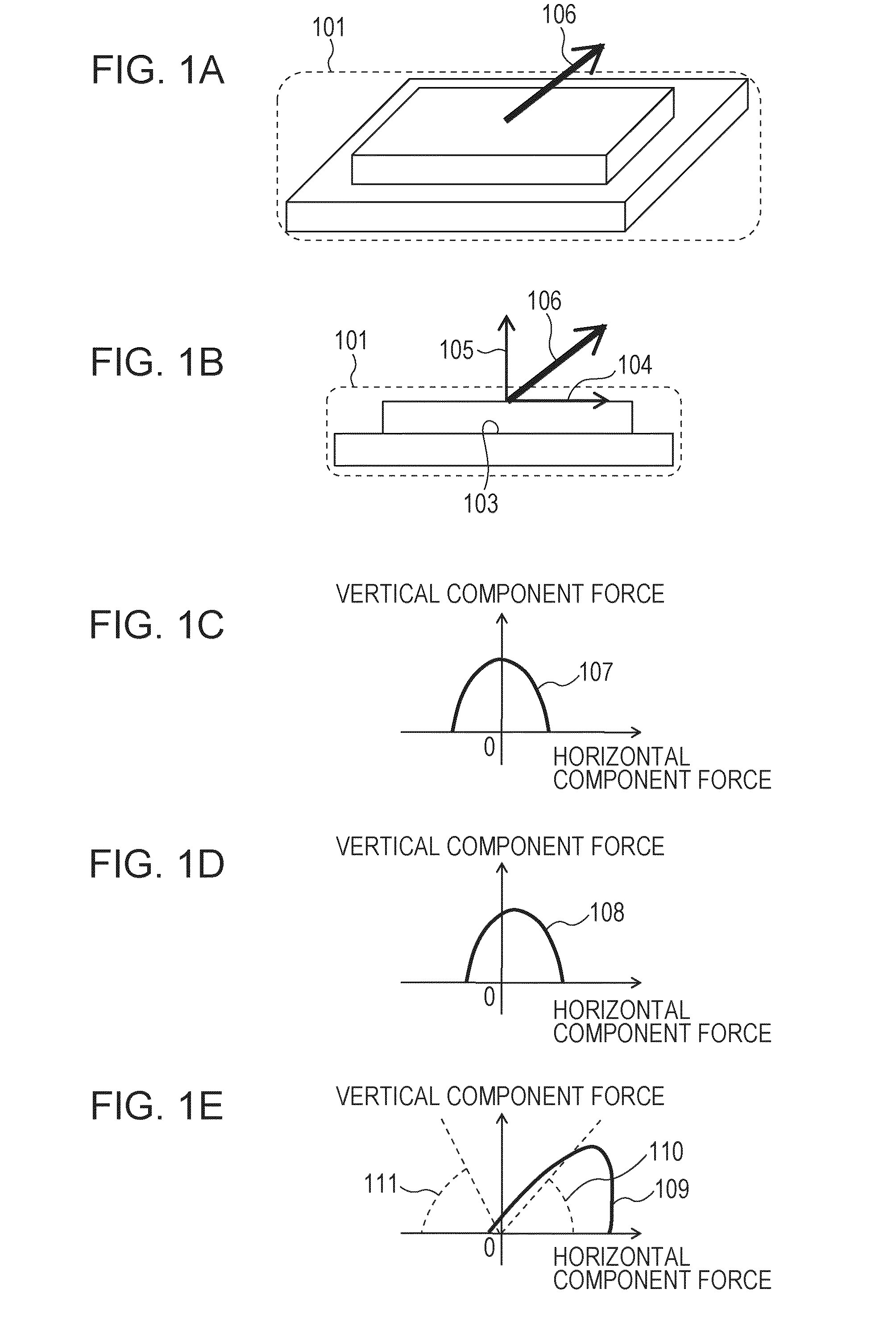
[0263]In the examples and reference examples described below, the level of the directional dependency of the adhesion force or the adhesion profile of a single protrusion (elastic structure) is described.
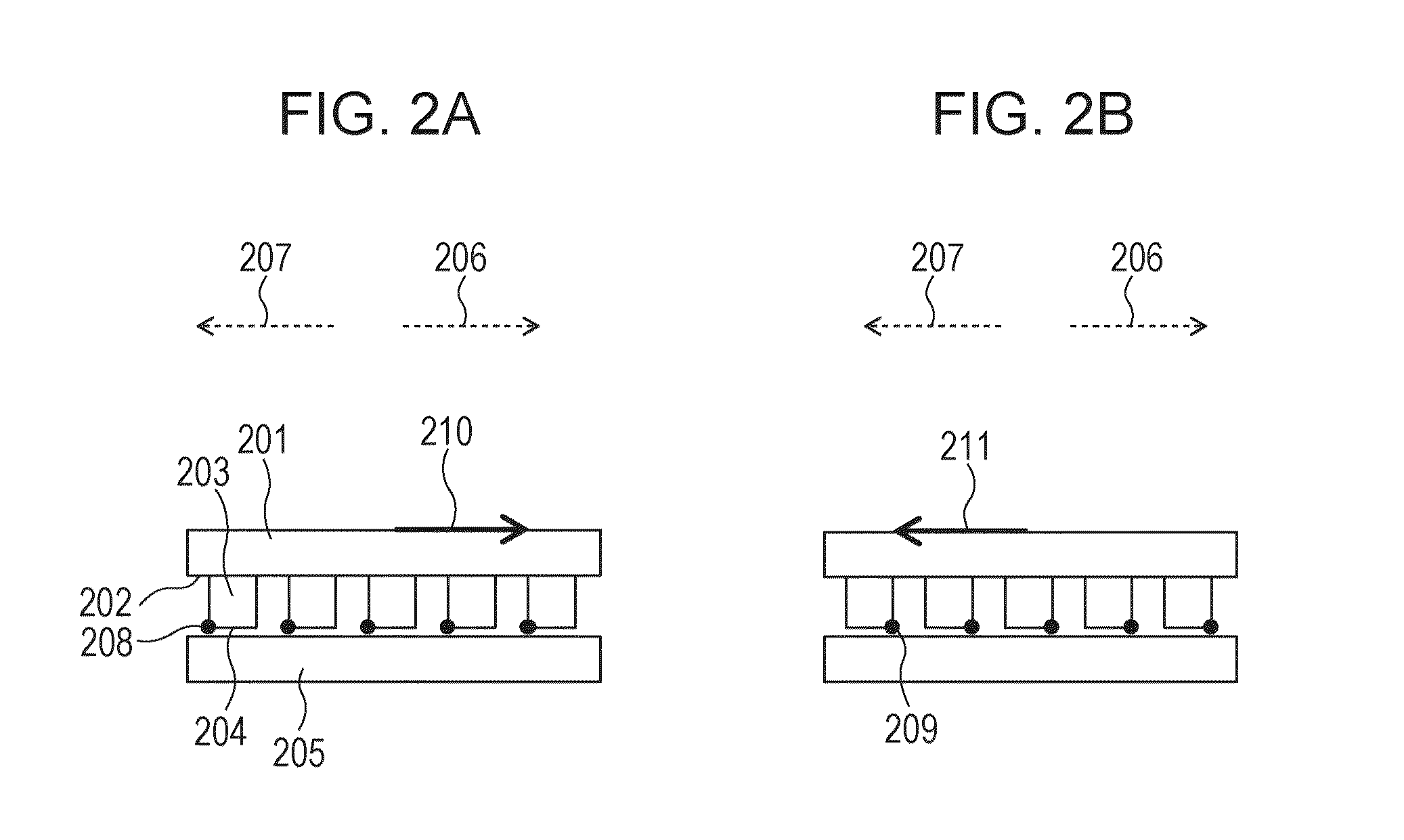
[0264]The adhesion property of the bonding member including multiple elastic structures is expressed by the sum total of the adhesion properties of the individual elastic structures. Thus, a bonding member as a whole has directionally dependent adhesion force equivalent to that described in these examples and reference examples.
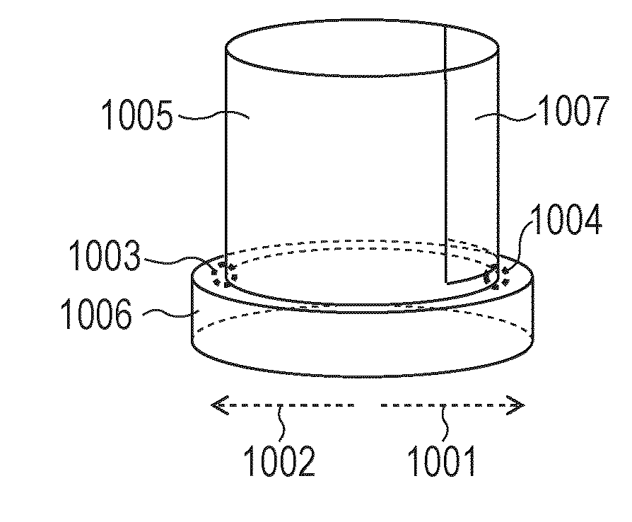
[0265]In the following examples and reference examples, the release portion was estimated by performing a rough stress analysis before performing a specific adhesion force analysis. In either example, a first release portion 1003 may be regarded as an end of the bottom face of an elastic structure 1005 in a second direction 1002 and a second release portion 1004 may be regarded as an end of the bottom face of the elastic structure 1005 in a first direction 10...
reference example 2
Analysis on Adhesion Profile of Protrusion Having Asymmetric Horizontal Cross Section
[0275]FIG. 10B illustrates the shape of an analytic model.
[0276]The shape of a protrusion (elastic structure) 1005 disposed on the surface of the bonding member was defined as a triangular prism having a height of 10 μm and having a horizontal cross section shaped in an isosceles triangle having a base of 10 μm and a height of 10 μm. The modulus of elasticity and the Poisson's ratio were respectively determined as 0.29 MPa and 0.45.
[0277]The modulus of elasticity and the Poisson's ratio of the substrate were respectively determined as 80 GPa and 0.21. The shape of the substrate 1006 for structure analysis was defined as a triangular prism having a height of 2 μm and having a cross section shaped in an isosceles triangle having a base of 11 μm and a height of 11 μm.
[0278]Here, the first direction 1001 is defined as a direction perpendicular to the base of the cross section and extending from the base...
PUM
| Property | Measurement | Unit |
|---|---|---|
| Shape | aaaaa | aaaaa |
| Adhesivity | aaaaa | aaaaa |
| Energy | aaaaa | aaaaa |
Abstract
Description
Claims
Application Information
 - R&D
- Intellectual Property
- Life Sciences
- Materials
- Tech Scout
- Unparalleled Data Quality
- Higher Quality Content
- 60% Fewer Hallucinations
Browse by: Latest US Patents, China's latest patents, Technical Efficacy Thesaurus, Application Domain, Technology Topic, Popular Technical Reports.
© 2025 PatSnap. All rights reserved.Legal|Privacy policy|Modern Slavery Act Transparency Statement|Sitemap|About US| Contact US: help@patsnap.com


