
Liquid mechanical seal device applicable to variable pressure environment

A mechanical sealing device and liquid technology, which is applied in the direction of engine sealing, mechanical equipment, engine components, etc., can solve the problems of poor adaptability to deep submersibles, etc., and achieve the effects of improving system stability, low leakage rate, and improving stability

Active Publication Date: 2017-12-22
ZHEJIANG UNIV OF TECH
View PDF5 Cites 8 Cited by
  • Summary
  • Abstract
  • Description
  • Claims
  • Application Information

AI Technical Summary

Problems solved by technology

[0005] The present invention aims to overcome the problem that the existing mechanical seal structure has poor adaptability to marine equipment or submersibles in oceans or rivers and other waters, and provides a semi-adaptive liquid mechanical seal suitable for waters. Sealing device, the structure of the mechanical seal system changes with the pressure of the medium, and its balance ratio or / and closing force change accordingly, thereby increasing the ability of the mechanical seal to adapt to the environment, improving the performance and service life of the mechanical seal

Method used


Image

  • Liquid mechanical seal device applicable to variable pressure environment
  • Liquid mechanical seal device applicable to variable pressure environment
  • Liquid mechanical seal device applicable to variable pressure environment

Examples


Embodiment Construction

[0025] The technical solution of the present invention will be described in detail below in conjunction with the accompanying drawings.

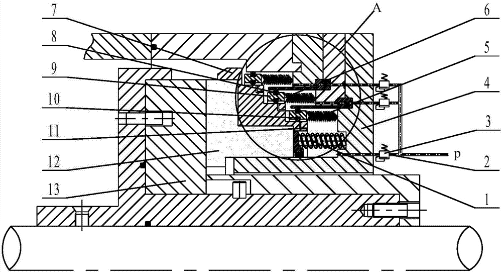
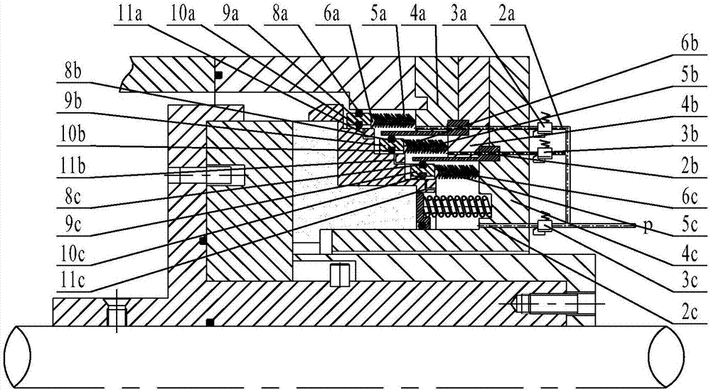
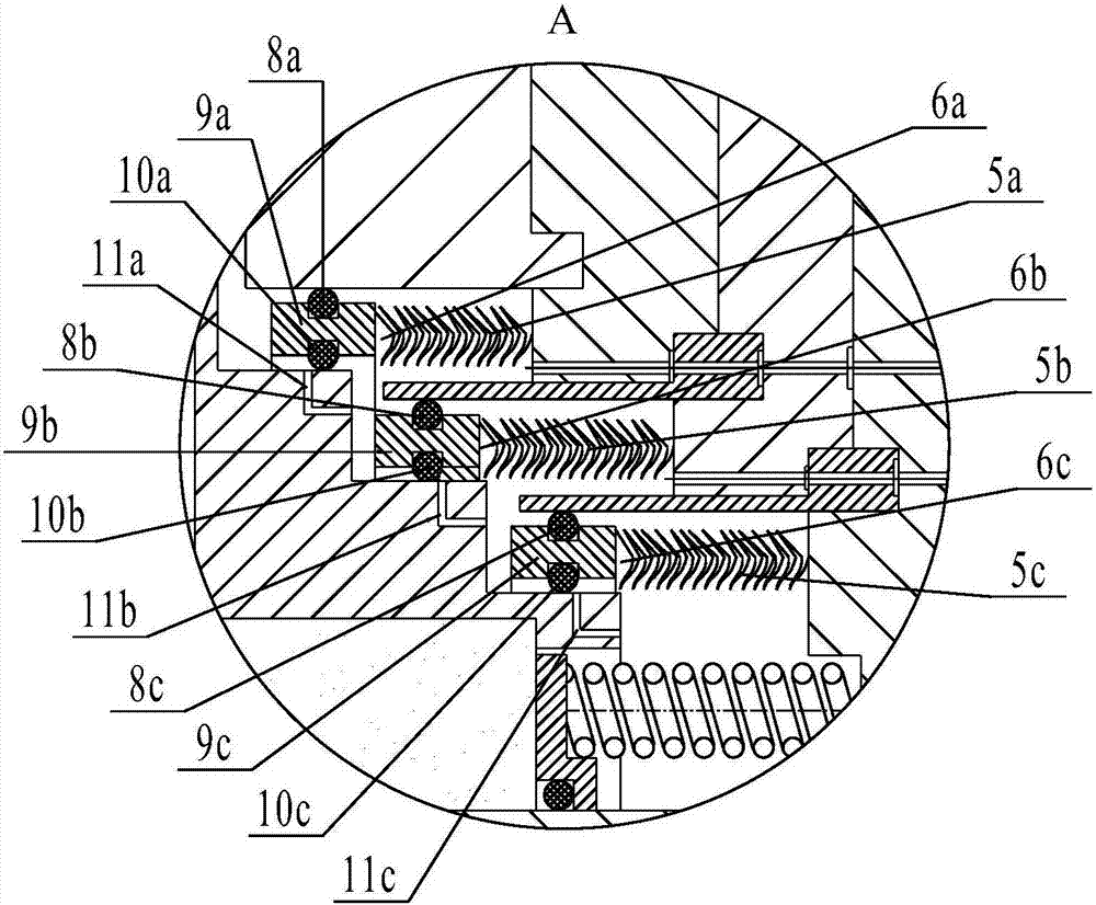
[0026] Description of numbers in the figure: 1-elastic element; 2-drainage pipe (2a-first-level discharge pipe; 2b-secondary discharge pipe; 2c-third-stage liquid discharge pipe); 3-direct-acting overflow valve ( 3a-one-stage direct-acting relief valve; 3b-two-stage direct-acting relief valve; 3c-three-stage direct-acting relief valve); 4-gland (4a-one-stage gland; 4b-two-stage Gland; 4c-three-stage gland); 5-metal bellows (5a-first-stage metal bellows; 5b-second-stage metal bellows; 5c-three-stage metal bellows); 6-pressure regulating slide valve (6a -first-stage pressure regulating slide valve; 6b-two-stage pressure regulating slide valve; 6c-three-stage pressure regulating slide valve); 7-pressure regulating overflow ring; 8-outer elastomer sealing ring (8a-first-stage outer elastomer Sealing ring; 8b-secondary outer elastomeric sealing ...


PUM


Abstract

The invention discloses a liquid mechanical seal device applicable to a variable pressure environment. The device comprises a rotational seal ring, a stationary seal ring, an elastic component, liquid drain tubes, direct-action overflow valves, multiple stages of pressure-regulating slide valves and multiple stages of glands. Each pressure-regulating slide valve comprises a piston, an elastic body seal ring, a metal corrugated pipe and a pressure-regulating overflow ring. The pistons slide axially on the pressure-regulating overflow rings. Each elastic body seal ring comprises an inner ring body and an outer ring body which are mounted on the inner side and the outer side of a piston ring in the radial direction of the piston ring correspondingly. Multiple stages of pressure-regulating overflow holes are machined in the pressure-regulating overflow rings and communicate with two adjacent medium cavities. Opening of the multiple stages of pressure-regulating overflow holes is controlled by the algebra and amplitude of the piston end surface force, the metal corrugated pipe elastic force and the friction force between the inner elastic body seal ring bodies and the outer elastic body seal ring bodies; and the multiple stages of pressure-regulating slide valves and the corresponding glands are mounted from left to right in sequence, and bolts are connected with a machine shell to achieve press sealing.

Description

technical field [0001] The invention relates to the design field of liquid mechanical sealing devices, in particular to a liquid mechanical sealing device suitable for variable pressure environments, especially suitable for mechanical sealing devices for shaft ends of various submersible rotating equipment in ocean and river environments. Background technique [0002] In water environment such as rivers, lakes and oceans, the pressure of the submersible is not constant, and the pressure increases by 1MPa every time it dives 100m, so the water pressure in the water environment changes continuously with the submersible depth. A great feature. For the existing liquid sealing device, the spring force provided by the elastic element and the balance ratio of the mechanical seal are fixed. As the submersible dives and rises, as the external pressure of the equipment changes continuously, the mechanical seal During the operation, it will face problems such as sharp changes in the s...

Claims


Application Information

Patent Timeline
IPC IPC(8): F16J15/34
CPCF16J15/3448F16J15/3452F16J15/346
Inventor 彭旭东金杰孟祥铠江锦波李纪云赵文静
Owner ZHEJIANG UNIV OF TECH
Learn More