
Control device for vehicle

a control device and vehicle technology, applied in the direction of process and machine control, battery/fuel cell control arrangement, instruments, etc., can solve the problems of unpleasant driving sensation, rapid rise in engine rotation speed, etc., to inhibit the rise of soc, reduce the energy loss of boost converter and inverter, and consume electrical power

Inactive Publication Date: 2015-10-01
TOYOTA JIDOSHA KK
View PDF3 Cites 6 Cited by
  • Summary
  • Abstract
  • Description
  • Claims
  • Application Information

AI Technical Summary

Benefits of technology

The patent describes a method to decelerate without causing discomfort by reducing the engine's rotation speed and avoiding an increase in temperature. This is achieved by using a boost converter that increases the output voltage, which in turn reduces energy loss and enables the vehicle to use regenerative braking to consume excess power. The method prevents discomfort while still allowing for efficient braking and reduced fuel consumption.

Problems solved by technology

Rapid rise in engine rotation speed without also shifting down during deceleration gives an unpleasant sensation to the driver.

Method used


Image

  • Control device for vehicle
  • Control device for vehicle
  • Control device for vehicle

Examples


Embodiment Construction

[0020]Embodiments of the present invention will be described in the following based on the drawings. The present invention is not limited by the embodiments described herein.

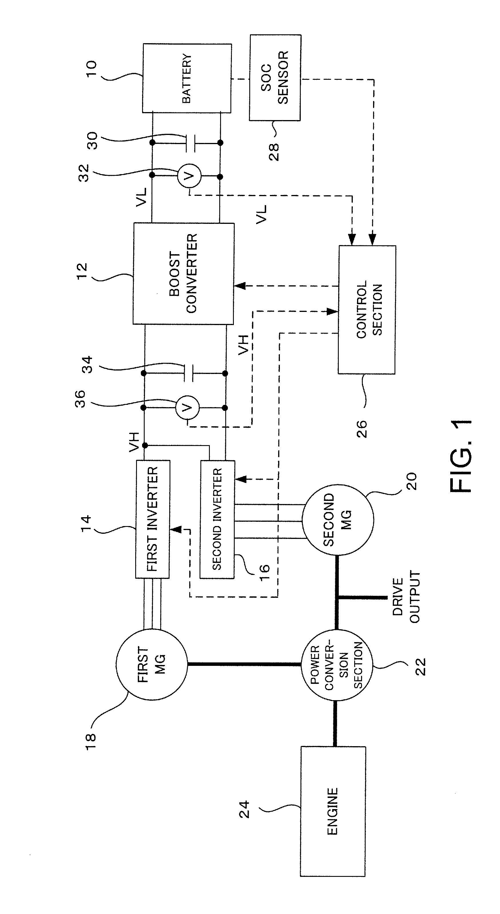
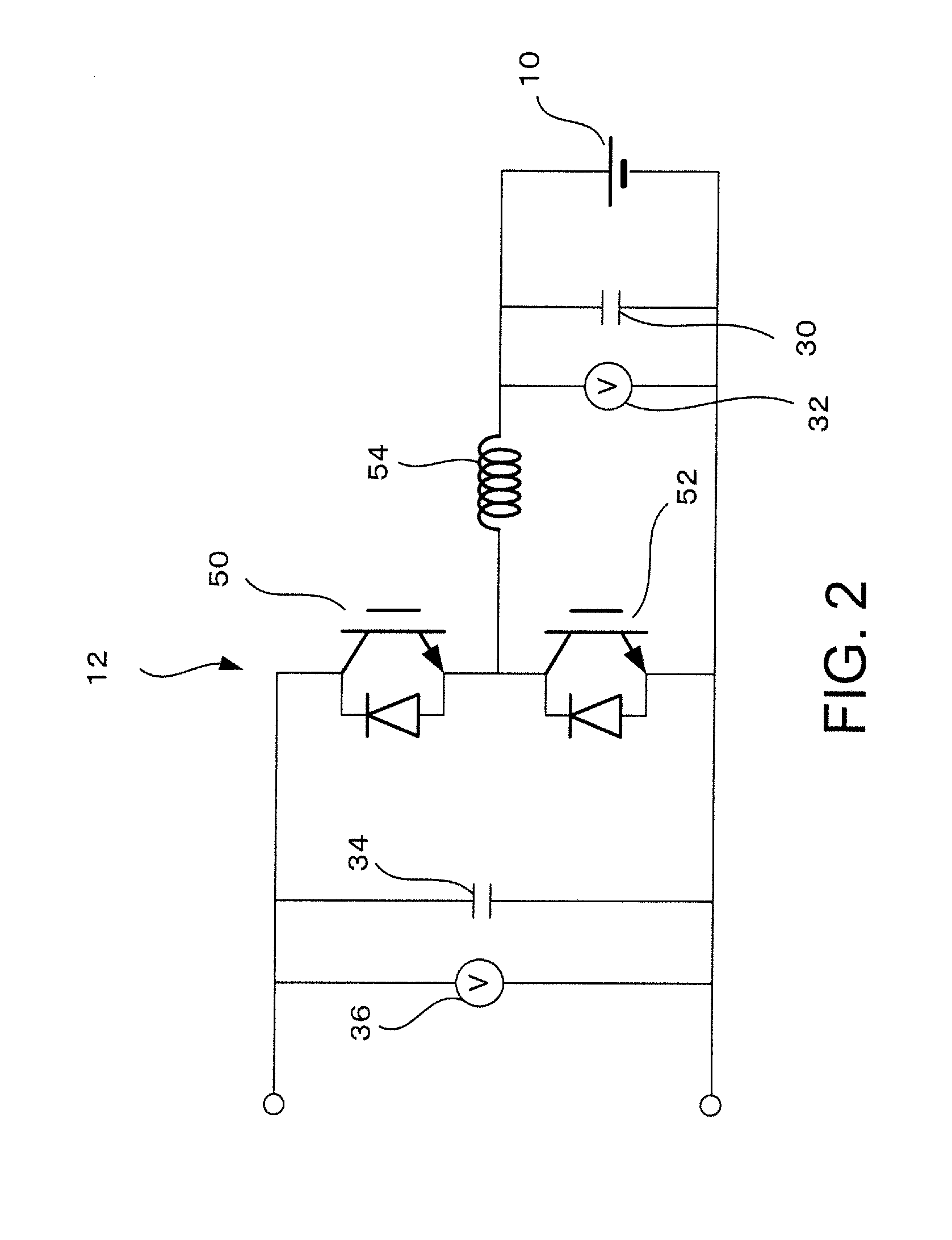
[0021]FIG. 1 is a schematic block diagram showing a drive system for a hybrid vehicle. Direct current output of a battery 10 is boosted by a boost converter 12, and then supplied to a first inverter 14 and a second inverter 16. A first MG (motor generator) 18 for electricity generation is connected to the first inverter 14, and a second MG (motor generator) 20 for drive is connected to the second inverter 16.

[0022]Output shafts of the first MG 18 and the second MG 20 are connected to a power conversion section 22, and an output shaft of an engine 24 is also connected to this power conversion section 22. Also, rotation of an output shaft connecting the conversion section 22 and the second MG 20 is transmitted to a drive shaft of the vehicle as drive output, while output of the conversion section 22 and / or the sec...


PUM


Abstract

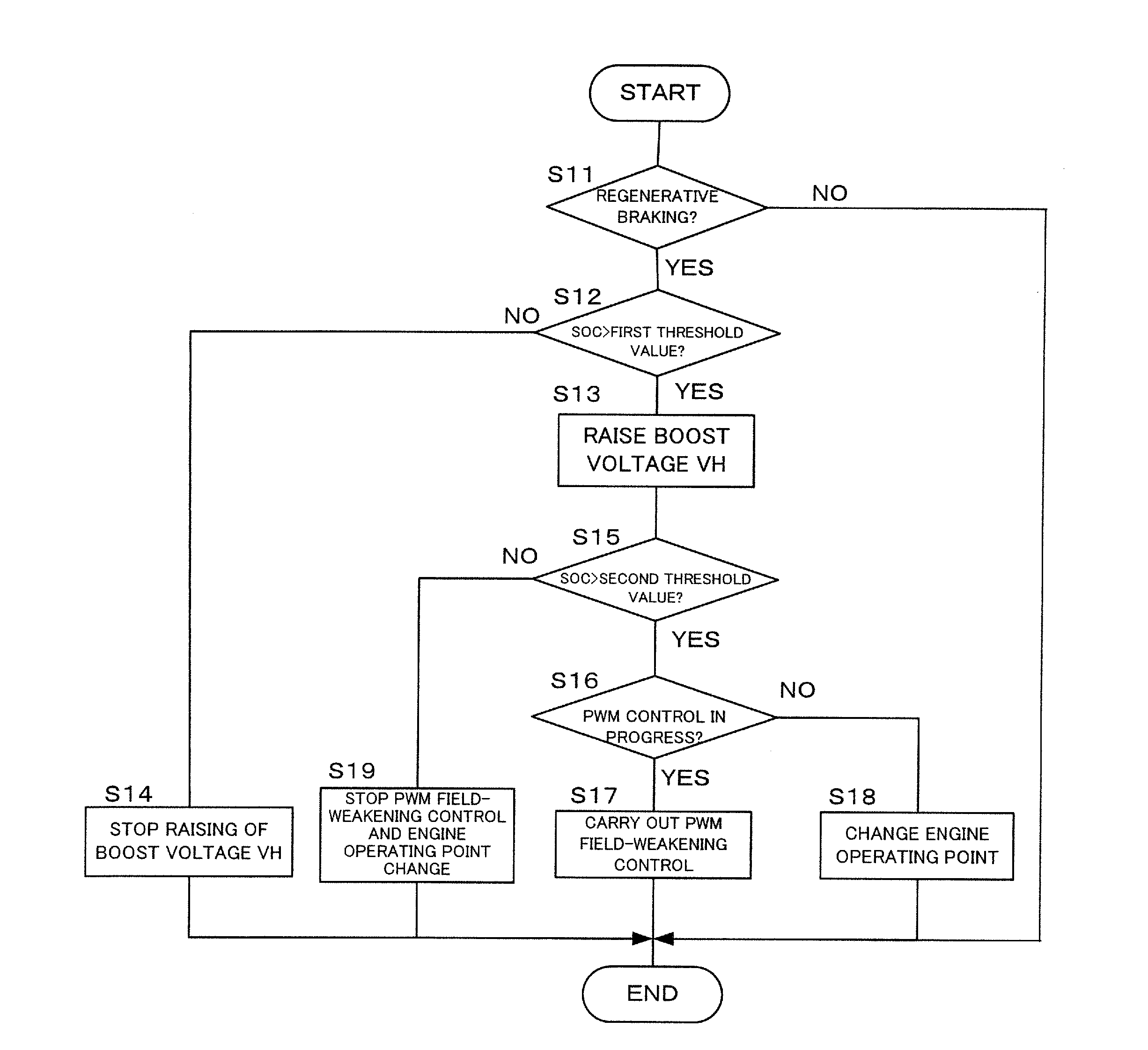
A vehicle control device includes a battery, a boost converter connected to the battery, for boosting battery voltage, a second inverter connected to the boost converter for carrying out direct current / alternating current conversion, a second MG connected to the second inverter, for outputting drive force, and an SOC sensor for detecting charged state of the battery. The control section, when the SOC that has been detected by the SOC sensor exceeds a first threshold value, raises the output voltage of the boost converter compared to when the SOC is below the first threshold value. In this way it is possible to sufficiently utilize regenerative braking and braking without any unpleasant feeling is possible.

Description

RELATED APPLICATION INFORMATION[0001]This application claims priority to Japanese Patent Application No. 2014-075068, filed on Apr. 1, 2014, the entire content of which is incorporated herein by reference.BACKGROUND[0002]1. Technical Field[0003]The present invention relates to a control device for a vehicle that efficiently consumes regenerative electrical power.[0004]Regenerative braking is used in hybrid vehicles (HV) and electric vehicles (EV) at the time of deceleration, and a battery is charged using recovered electrical power.[0005]Here, if a battery charged state (SOC) is already high, no further charging can be carried out. Specifically, excessive charging of the battery would cause damage to the battery and so must be avoided.[0006]With patent publication 1, when SOC is high, engine operating point is changed and the engine forcibly turned to achieve deceleration utilizing engine loss. In this way it is possible to prevent excessive rise in SOC.PRIOR ART REFERENCES[0007]Pat...

Claims


Application Information

Patent Timeline
Patent Type & Authority Applications(United States)
IPC IPC(8): B60L7/18B60L11/18
CPCB60L7/18Y10S903/947B60L11/1862B60L11/1803B60L3/003B60L7/14B60L15/2009B60L2210/14B60L2210/40B60L2240/12B60L2240/36B60L2240/421B60L2240/423B60L2240/441B60L2240/443B60L2240/525B60L2240/547B60L2240/549B60L50/16B60L50/61B60L58/13Y02T10/62Y02T10/64Y02T10/70Y02T10/7072Y02T10/72B60L3/0046
Inventor SATO, RYOJI
Owner TOYOTA JIDOSHA KK
Learn More