Scraper blade for conveyor belts

a conveyor belt and scraper blade technology, applied in the direction of conveyor parts, cleaning, transportation and packaging, etc., can solve the problems of reducing the connection strength between the scraper blade and the insert, increasing the likelihood of an air bubble becoming trapped between the blade and the insert of the conventional scraper blade, and reducing the effect of the recess shape, so as to improve the connection strength and provide durability and strength. the effect of the connection

Active Publication Date: 2015-10-01
FLEXIBLE STEEL LACING
View PDF0 Cites 4 Cited by
  • Summary
  • Abstract
  • Description
  • Claims
  • Application Information

AI Technical Summary

Benefits of technology

[0005]In accordance with one aspect of the invention, a scraper blade is provided having an improved connection strength between a blade body of resilient material and an insert molded in situ with the blade body. The blade body has a pair of laterally spaced depending leg portions and the insert has a pair of laterally spaced side wall portions. The insert laterally spaced wall portions have variable wall thicknesses and laterally outwardly facing sides that extend along corresponding inwardly facing sides of the blade body depending leg portions. The scraper blade includes a plurality of recesses in each of the insert side wall portions with an undercut configuration and a plurality of projections of the blade body lower portion that extend laterally inward and fill the corresponding recesses in which the projections are received. The plurality of recesses in each of the insert side wall portions and the projections of the blade body lower portion that extend laterally into the recesses provide multiple, robust anchor locations for the depending leg portions of the blade body to the side wall portions of the insert. The multiple anchor locations resist loading, including bending moments, applied to the blade body during conveyor belt operations which act to pull the resilient blade body leg portions away from the rigid insert side wall portions. The scraper blade herein thereby provides durability and strength of the connection between the blade body and the insert during conveyor belt operations without the need for pretreating the insert for this purpose.
[0006]In one form, the plurality of recesses include neckdown regions that face laterally outward and the projections have narrow neck portions that extend laterally inward in the neckdown regions. The recesses have enlarged recessed regions and the projections have corresponding enlarged lateral end portions in the enlarged recessed regions. The side wall portions extend vertically generally orthogonal to the laterally extending projection neck portions. This locates the projection neck portions such that the neck portions are placed primarily in tensile loading during conveyor belt operations to maximize the strength of the connection between the blade projections and the insert recesses for a blade body made of a material such as urethane which has a much higher tensile strength than flexural strength. Thus, the scraper blade is configured and arranged to subject the material of the blade body projections to the type of loading that the projections are best able to resist, which increases the durability and strength of the scraper blade.
[0007]In one form, the plurality of recesses having an undercut configuration are free of sharp corners, edges, and / or other sudden changes in geometries that capture debris during molding of the blade body onto the insert, such as dust dirt from storage of the insert. The presence of dust or other debris on a conventional metal insert as liquid blade material is poured into a mold having the conventional insert creates a surface tension on the liquid and encourages air bubbles to adhere to the debris which decreases the strength of the connection between the conventional blade and the insert. It has been discovered that the sharp corners, edges, and / or other sudden changes in the geometry of the conventional insert magnify the effect of the debris on the surface tension in the liquid blade material and further increase the likelihood of an air bubble becoming trapped between the blade and the insert of a conventional scraper blade. By contrast, the recesses of the insert side wall portions of the subject scraper blade have undercut configurations free of sharp corners, edges, and / or other sudden changes in geometry. The smooth geometry of the recesses reduces the effect of the shape of the recesses on any debris that are present in the recesses during molding of the blade body onto the insert. In this manner, the recesses having undercut configurations without sharp corners, edges, and / or other sudden changes in geometry provide a more resilient molding process that is less effected by the presence of debris in the recesses of the insert.
[0008]In accordance with another aspect of the present invention, a scraper blade for a conveyor belt is provided with an improved connection strength between a molded blade body of resilient material and an insert molded in situ with the blade. The molded blade body has a lower pair of laterally spaced leg portions and the insert has a pair of laterally spaced side wall portions with laterally outwardly facing sides that extend along corresponding inwardly facing sides of the blade body leg portions. The scraper blade has a plurality of interlocking undercut recesses and complimentary projections of the insert side wall portions and the blade body leg portions. The interlocking undercut recesses and complimentary projections are recessed laterally into the insert side wall portions to maximize the lateral thickness of the blade body leg portions. By maximizing the lateral thickness of the blade body leg portions, a larger cross-section of the molded blade body is subjected to tension and other loading during operation of the conveyor such that the molded blade is more durable.
[0009]This approach stands in contrast to some conventional scraper blades having laterally extending arms. For these conventional scraper blades the longer the laterally extending arms were, the higher the resistance to the blade pulling off of the metal insert. However, making the laterally extending arms of the insert longer would produce a corresponding narrowing of the lateral thickness of the blade between the insert laterally extending arms and outer lateral surfaces of the scraper blade. The recessed interlocking undercut recesses and projections of the blade body and the insert thereby provide both a secure connection between the blade body and the insert as well as a maximized lateral thickness of the blade leg portion which increases the durability and strength of the blade body.
[0010]In one form, the plurality of interlocking undercut recesses and complimentary projections include a plurality of interlocking recesses and projections that are recessed laterally into each of the insert side wall portions. Because the plurality of interlocking recesses and projections are recessed into each insert side wall portion, the lateral thickness of the blade leg portions may be maximized despite providing multiple anchor locations between the insert along each insert side wall portion. The maximized lateral thickness of the blade leg portions provides a wide section of blade material to transfer loading to all of the recesses and projections along each insert side wall portion.

Problems solved by technology

The presence of dust or other debris on a conventional metal insert as liquid blade material is poured into a mold having the conventional insert creates a surface tension on the liquid and encourages air bubbles to adhere to the debris which decreases the strength of the connection between the conventional blade and the insert.
It has been discovered that the sharp corners, edges, and / or other sudden changes in the geometry of the conventional insert magnify the effect of the debris on the surface tension in the liquid blade material and further increase the likelihood of an air bubble becoming trapped between the blade and the insert of a conventional scraper blade.
The smooth geometry of the recesses reduces the effect of the shape of the recesses on any debris that are present in the recesses during molding of the blade body onto the insert.

Method used


Image

  • Scraper blade for conveyor belts
  • Scraper blade for conveyor belts
  • Scraper blade for conveyor belts

Examples


Embodiment Construction

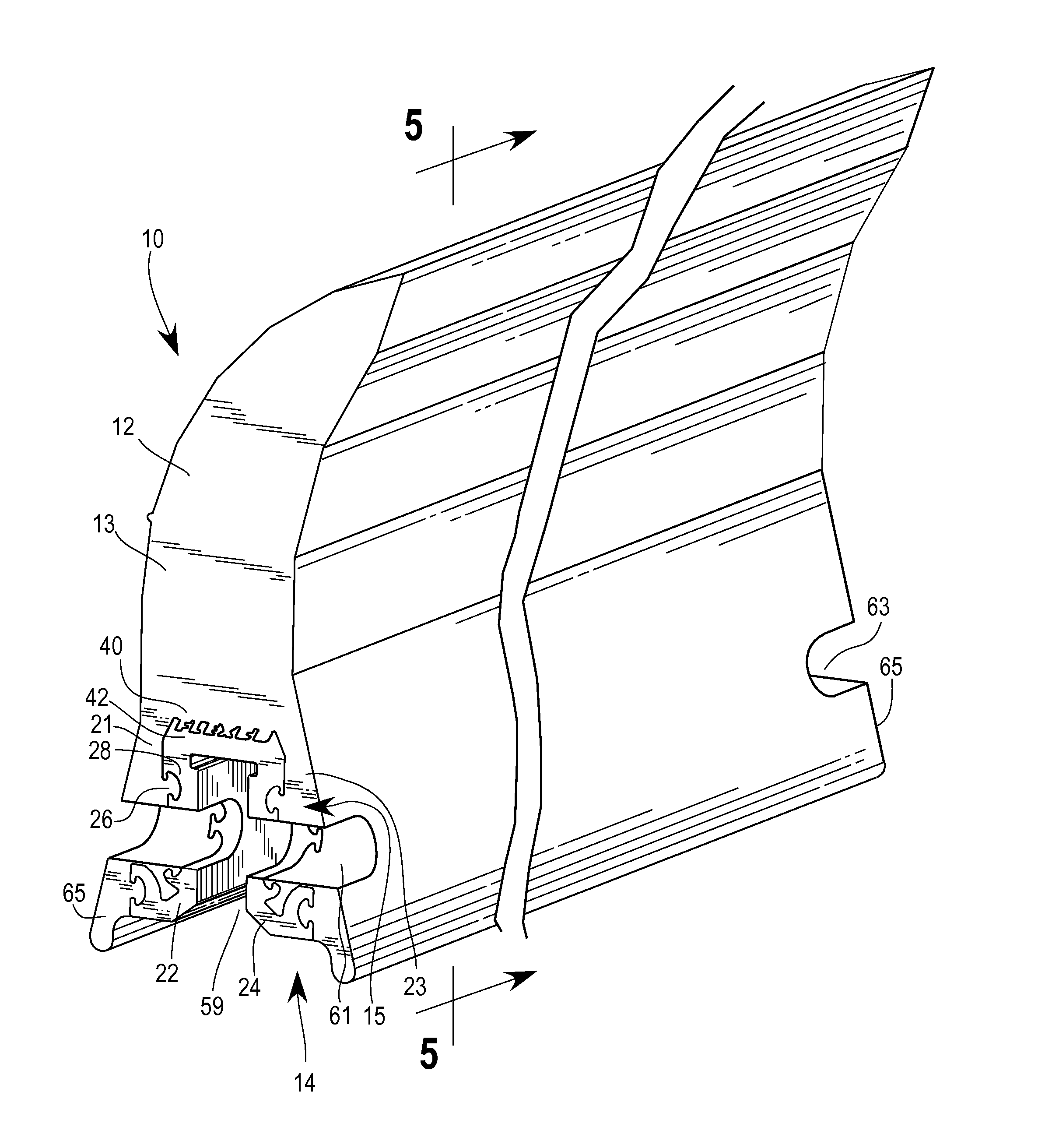
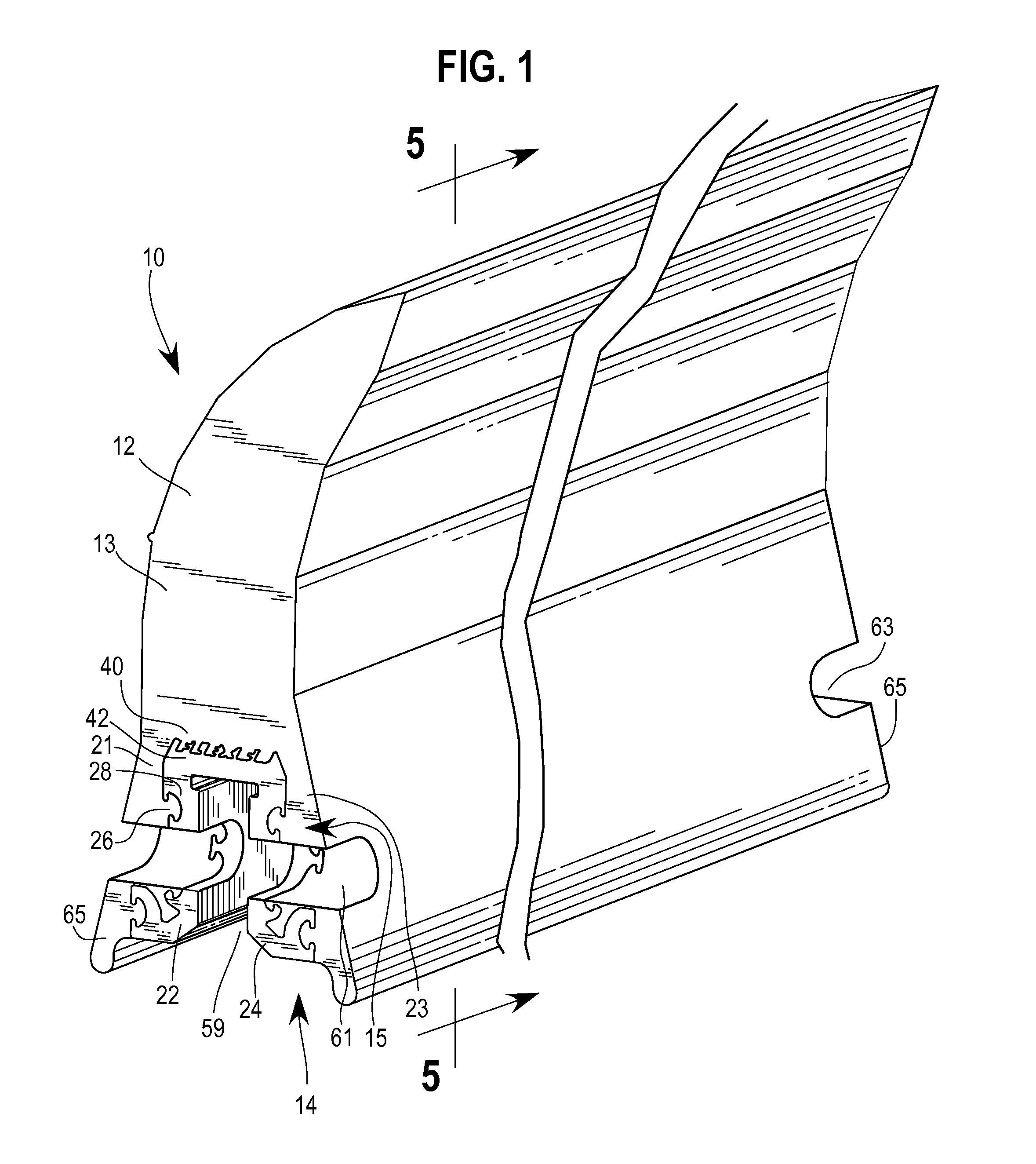
[0022]With reference to FIG. 1, a scraper blade 10 is provided having a blade 12 with a molded body 13 of resilient material and an insert 14 of molded in situ with the blade body 13. In one embodiment, the blade 12 is made of the first material and is molded onto the insert 14 which is made of a rigid second material. By rigid, what is meant is that the structure has the ability to generally retain its respective shape during normal handling and use. For example, the blade 12 may be made of urethane or an elastomer. The insert 14 may be made of a rigid material, such as metallic material or a rigid thermoplastic. Further examples of the insert 12 material include aluminum, high-density polyethylene, and nylon, and other extruded or injection molded plastics.

[0023]The scraper blade 10 has an interface 15 between the blade 12 and the insert 14 that securely fixes the blade 12 with improved strength and durability over some prior scraper blades utilizing mold locking of a blade onto a...


PUM


Abstract

In one aspect, a scraper blade for a conveyor belt is disclosed that provides improved strength and durability of a connection between a resilient blade body and an insert molded in situ with the blade body. The blade body has an upper portion with a scraping tip and a lower portion with a pair of laterally spaced depending leg portions. The insert has a pair of laterally spaced side wall portions with variable wall thicknesses and laterally outwardly facing sides that extend along laterally inwardly facing sides of the blade body leg portions. Each insert side wall portion and the blade body lower portion include a plurality of recesses having an undercut configuration and a plurality of projections extending laterally and filling the corresponding recesses in which the projections are received to keep the blade body and the insert connected together under loading during conveyor belt operations.

Description

FIELD OF THE INVENTION[0001]The invention relates to conveyor belt systems and, more particularly, to scraper blades for conveyor belts.BACKGROUND OF THE INVENTION[0002]Scraper blades may be used to scrape material off of conveyor belts. Some conventional approaches utilize a tensioning mechanism that maintains a section of the scraper blade against the conveyor belt. In one approach, the scraper blade has a urethane tip for scraping the conveyor belt and a metal insert used for mounting the scraper blade to an elongate support member assembly that extends across the belt. The urethane tip is molded onto the metal insert by pouring molten urethane into a mold containing the metal insert and allowed to harden on the metal insert. The metal insert provides a rigid base for securely connecting the blade to the support member.[0003]A problem with scraper blades that utilize a urethane tip molded onto a metal insert is that the loading on the urethane tip during use of the scraper blade ...

Claims


Application Information

Patent Timeline
Patent Type & Authority Applications(United States)
IPC IPC(8): B65G45/14
CPCB65G45/14B65G45/12
Inventor DEVRIES, BRETT E.
Owner FLEXIBLE STEEL LACING
Why Eureka
Try Eureka