Clamp-On Drill String Wiper

a drill string wiper and clamping technology, which is applied in the direction of fluid removal, sealing/packing, and borehole/well accessories, etc., can solve the problems of inability to be handled directly by workers, fixed on the rig, and inconvenient to clean, etc., to facilitate the cleaning of external surfaces

Inactive Publication Date: 2015-10-01
MACHICEK DAVID
View PDF8 Cites 9 Cited by
  • Summary
  • Abstract
  • Description
  • Claims
  • Application Information

AI Technical Summary

Benefits of technology

[0008]In fulfillment of the above and further objectives, the present invention provides a clamp-on wiper device that facilitates the cleaning of the external surfaces of sections of a drill string or drill pipe to remove earth, drilling mud, petroleum products, and other solid/liquid mixtures of such compounds while the drill string or drill pipe is being handled on a drill platform. The pipe wiper includes a split cylinder with two halves hinged together and fitted with handles on each half. Internal to each half cylinder are a number of h

Problems solved by technology

Although this process can be dangerous at times, its safety and efficiency depends on the care taken by the workers in the handling of equipment, and to some extent, the ability of the workers to operate within a relatively clean and clear environment.
For the most part, these existing systems are fixed on the rig (i.e., are not portable or capable of being handled directly by the workers) and require that an end of the drill string (typically the bit end of the string) pass longitudinally through the cleaning sys

Method used


Image

  • Clamp-On Drill String Wiper
  • Clamp-On Drill String Wiper
  • Clamp-On Drill String Wiper

Examples


Embodiment Construction

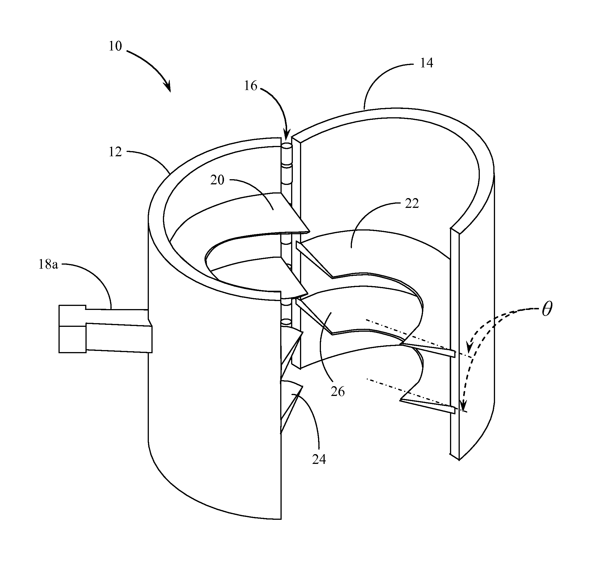
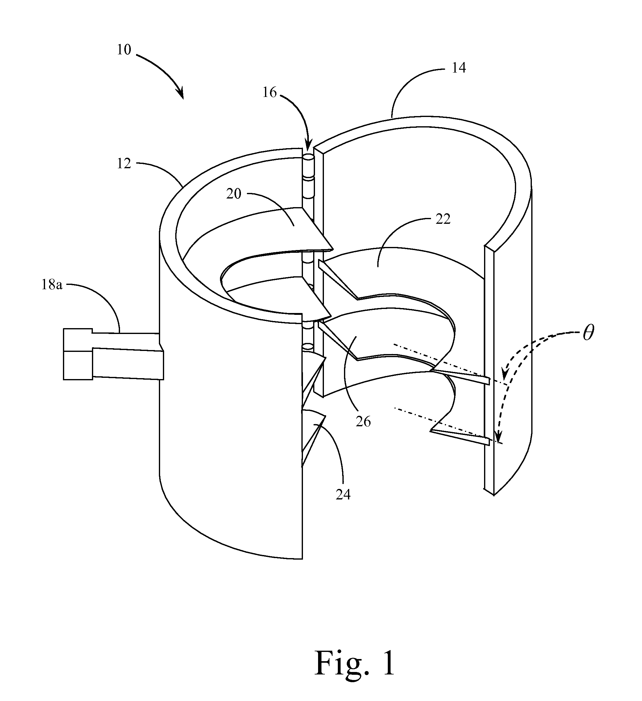
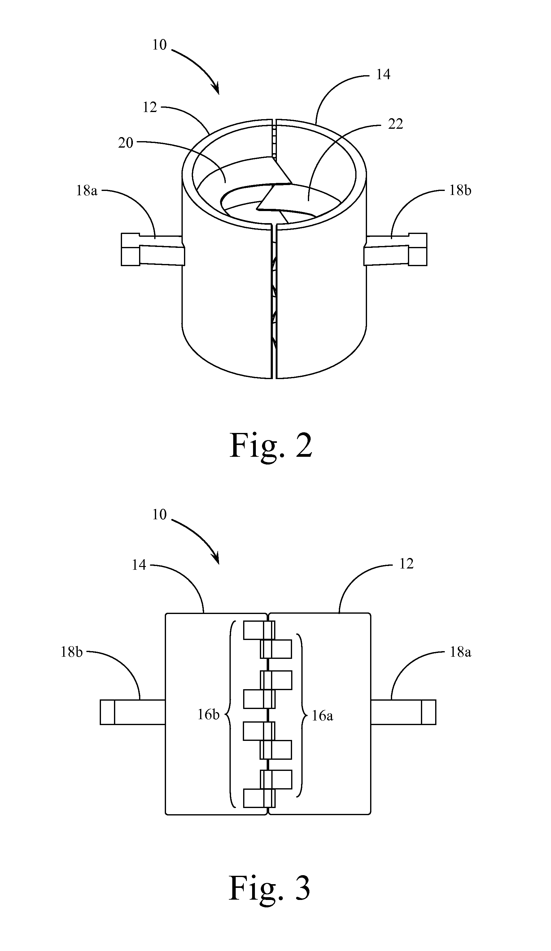
[0017]Reference is made first to FIG. 1 for a perspective view of the wiper device of the present invention shown in a partially open configuration apart from the drill string or drill pipe. The perspective view shown in FIG. 1 provides the orientation of the device that would be required for the placement and positioning of the wiper onto a drill string or drill pipe. Pipe wiper 10 is generally constructed of two half cylindrical shells, first half shell 12 and second half shell 14. These half cylindrical shells are connected to each other through hinge array 16. In a preferred embodiment of the invention, the two half shells 12&14 are constructed from a cylindrical section of large PVC pipe that is split longitudinally with the two resulting half cylinders attached one to the other with hinge array 16.

[0018]Positioned on the outside face of each of first half shell 12 and second half shell 14 are first side handle 18a and second side handle 18b (18b not shown in the view of FIG. 1...


PUM


Abstract

A clamp-on wiper that facilitates the cleaning of external surfaces of sections of a drill string or drill pipe to remove earth, drilling mud, and other solid/liquid compounds while the drill string is being handled on a drilling platform. The pipe wiper includes a split cylinder with two halves hinged together, each with a handle. Internal to each half cylinder are a number of half circle flexible squeegees that conform to the outside diameter of the drill string when the device is closed. The device may be handled by an individual and positioned around the pipe without the need for access to the end of the drill string. The user may close and hold the pipe wiper around the pipe while the drill string is moving upward so as to wipe liquid and solid debris from the pipe as it is raised.

Description

BACKGROUND OF THE INVENTION[0001]1. Field of the Invention[0002]The present invention relates generally to tools and equipment used in oil field drilling and pipe handling operations. The present invention relates more specifically to a device that facilitates the cleaning of the external surfaces of sections of drill string or drilling pipe to remove mud, drilling mud, petroleum products, and solid / fluid mixtures of such compounds, while the drill string or pipe is being handled on a drilling rig platform.[0003]2. Description of the Related Art[0004]A great deal of science and technology has been devoted to exploration and drilling for fossil fuels in recent years. The high cost of petroleum exploration and drilling operations has increased the need for efficiency in the operation of drilling rigs and the like. One aspect of the drilling process that is critical to efficient exploration, drilling, and production, is the safe and timely process of operating a drilling rig and platfo...

Claims


Application Information

Patent Timeline
IPC IPC(8): E21B37/02
CPCE21B37/02E21B33/08
Inventor MACHICEK, DAVID
Owner MACHICEK DAVID
Why Eureka
Try Eureka