Vibration damping device

a technology of vibration damping and bracket member, which is applied in the direction of shock absorbers, machine supports, other domestic objects, etc., can solve the problems of increasing the weight of the bracket member for the purpose of securing the durability, and the portion of the bracket member mounted to the vehicle is more difficult to secure the durability, etc., to achieve the effect of improving the durability of parts, and reducing the amount of stress

Inactive Publication Date: 2015-10-01
SUMITOMO RIKO CO LTD
View PDF16 Cites 17 Cited by
  • Summary
  • Abstract
  • Description
  • Claims
  • Application Information

AI Technical Summary

Benefits of technology

[0033]According to the twelfth aspect the stopper load transmitted from the input portion is exerted dispersedly against the abutting portion of the bracket member even over to the area closer to the mounting part, even if the acting position of the stopper load on the input portion of the second mounting member is away from the mounting part of the bracket. This reduces the moment of force exerted on the mounting part by the stopper load to reduce the amount of stress acting on the mounting structure of the bracket member for the vibration transmission system, thus improving the durability of the parts.
[0034]According to the present invention, the abutting portion between the first mounting member and the bracket member is indirectly abutted against each other through the input portion overlapped on the abutting portion through the abutting rubber. Therefore, the degree of freedom in setting the position and the working range of the stopper load on the bracket member is significantly improved as compared to the situation where the stopper load is directly inputted into the bracket member from the first mounting member, thus achieving reduction in the maximum stress and the like.

Problems solved by technology

However, according to US 2006 / 0043656, the first mounting member is abutted against the bracket member within a specific, limited area, which imposes a risk, that the stress brought by the stopper load acts on the limited area of the bracket member in a concentrated manner so that an increase in weight of the bracket member for the purpose of securing the durability can become a problem.
Also, if the mounting position of the bracket member to the vehicle is away from the input position of the stopper load, the moment of force acting on the mounted position sometimes becomes larger to make it more difficult to secure the durability of the portion of the bracket member mounted to the vehicle.

Method used


Image

  • Vibration damping device
  • Vibration damping device
  • Vibration damping device

Examples


Embodiment Construction

[0040]Embodiments of the present invention will be described below in reference to the drawings.

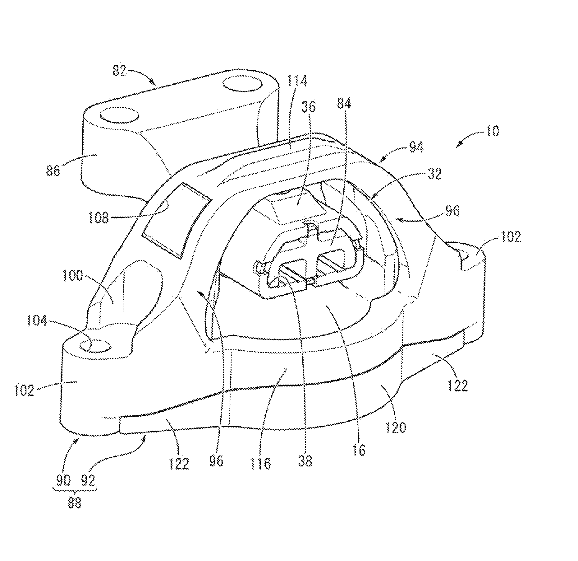
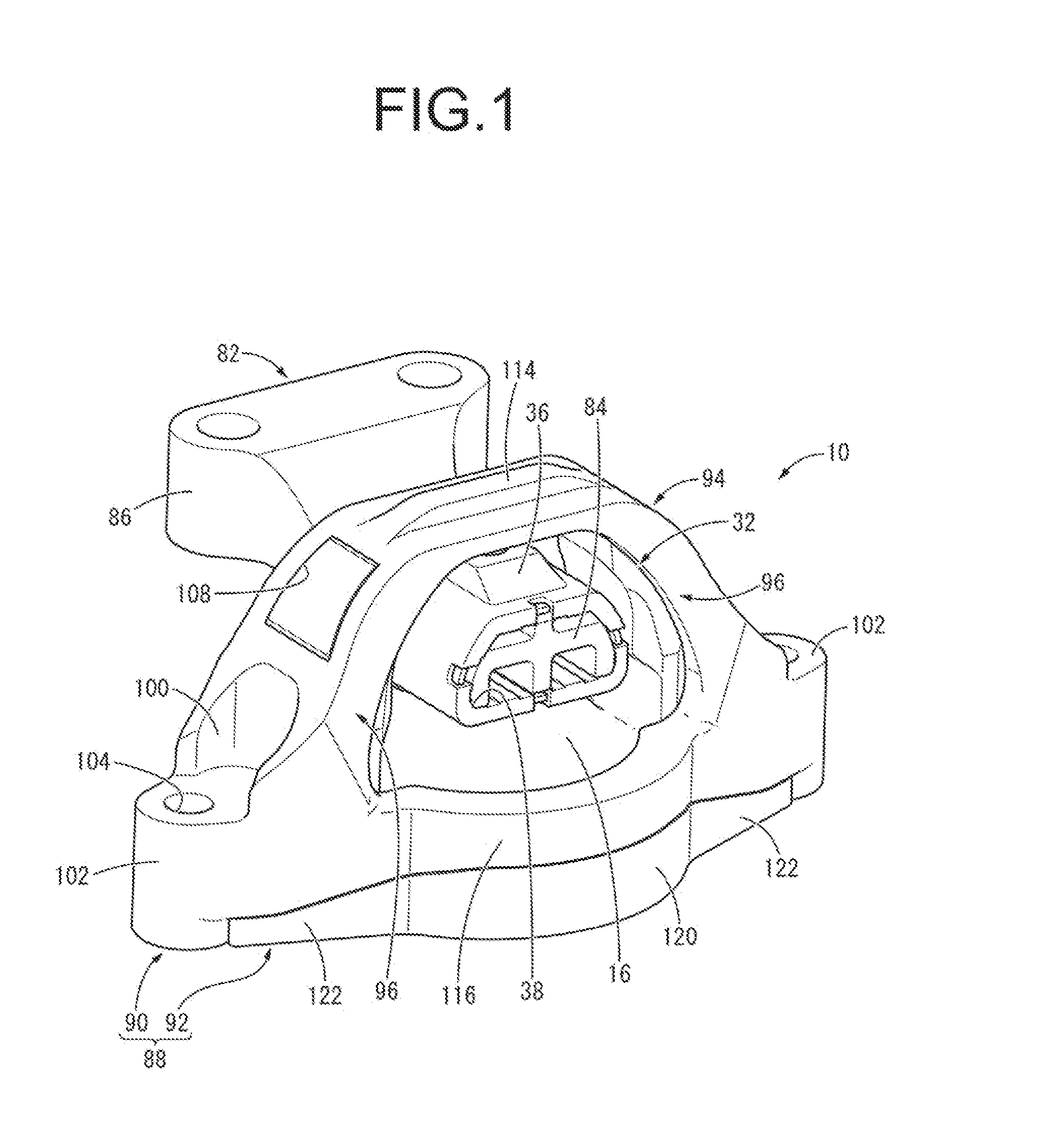
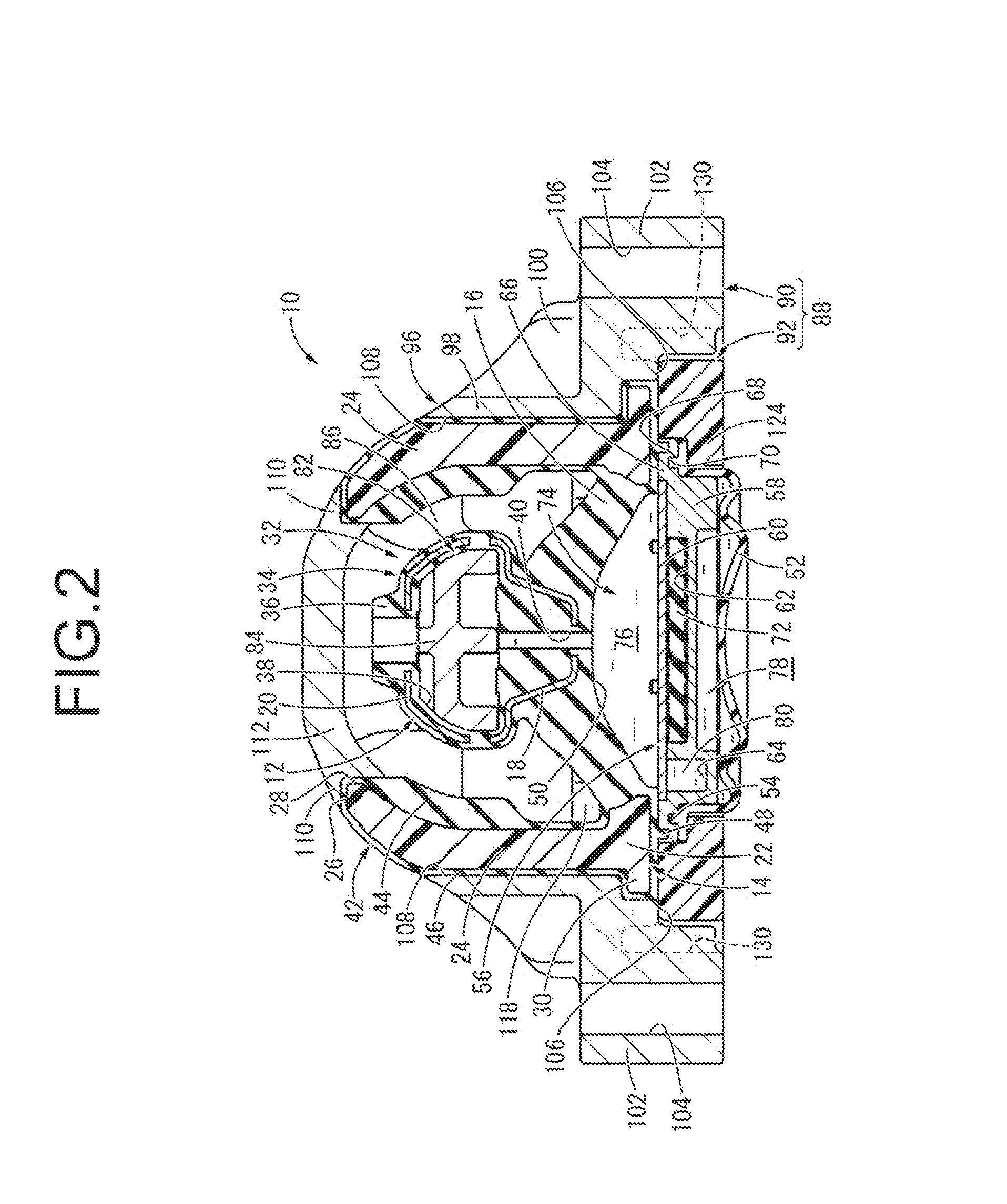
[0041]FIGS. 1 and 2 show an engine mount 10 for motor vehicles as a first, embodiment of the vibration damping device having the structure according to the present invention. The engine mount 10 has a structure where a first mounting member 12 and a second mounting member 14 are elastically connected to each other by a main rubber elastic body 16. In the following description, as a general rule the up-down direction means an up-down direction of the engine mount in a state of being mounted to a vehicle represented by the up-down direction in FIG. 2, the front-rear direction means a front-rear direction of the vehicle represented by the left-right direction in FIG. 2, and the left-right direction means a left-right direction of the vehicle represented by the direction perpendicular to the plane of the page of FIG. 2.

[0042]More specifically, the first mounting member 12 is a high-rigidity m...


PUM


Abstract

A vibration damping device including first and second mounting members elastically connected to each other by a main rubber elastic body, and a bracket member mounted to the second mounting member and providing a stopper for restricting displacement of the first mounting member relative to the second mounting member by means of abutment between the first mounting member and the bracket member. The second mounting member includes an input portion that faces the first mounting member at a given distance. The bracket member includes an abutting portion that faces the first mounting member with the input portion being interposed therebetween. An abutting rubber layer is provided on a surface of the input portion overlapped on the abutting portion. The stopper is constituted, by abutment between the first mounting member and the abutting portion via the input portion.

Description

INCORPORATED BY REFERENCE[0001]This is a Continuation of International Application No. PCT / JP2014 / 058898 filed on Mar. 27, 2014, the disclosure of which including the specification, drawings and abstract is incorporated herein by reference in its entirety.BACKGROUND OF THE INVENTION[0002]1 Field of the Invention[0003]The present invention relates to a vibration damping device to be used, for example, for engine mounts and the like on motor vehicles.[0004]2. Description of the Related Art[0005]Conventionally, there has been known a vibration damping device as a kind of vibration damping coupling body or a vibration damping supporting body interposed between the members constituting a vibration transmission system to couple or support the members each other in a vibration damping manner. The vibration damping device, as disclosed in U.S. Publication No. US 2006 / 0043656 for example, has a structure where a first moon ting member and a second mounting member are elastically connected by...

Claims


Application Information

Patent Timeline
Patent Type & Authority Applications(United States)
IPC IPC(8): F16F15/08F16M13/02
CPCF16M13/02F16F15/08F16F13/101F16F13/108
Inventor NAKAMURA, SATOKIDAITO, HIRONORIISHIGAKI, YUUKI
Owner SUMITOMO RIKO CO LTD
Why Eureka
Try Eureka