Metal framing layout square and a method of using same

a metal framing and layout square technology, applied in the field of framing systems, can solve the problems of affecting the installation of other components in the structure, the process of constructing a wood framing system is relatively slow, and the quality of the workmanship associated with the construction of wood framing is often poor, so as to achieve the effect of simple, cost-effective and efficien

Inactive Publication Date: 2015-10-01
LAMANNA MICHAEL +1
View PDF9 Cites 8 Cited by
  • Summary
  • Abstract
  • Description
  • Claims
  • Application Information

AI Technical Summary

Benefits of technology

[0021]In view of the foregoing needs, the present invention is directed to a simple, cost effective and efficient tool for measuring and marking layouts for metal framing systems for framing at least a portion of a wide variety of structures. Some of such structures include residential homes, commercial buildings, apartment and condominiums, office build-outs, utility buildings, and modular or kiosk structures. The framing systems for use with the present invention utilizes either rectangular or square metal tubing, or a combination thereof, and therefore has several advantages over existing wood framing systems.
[0022]The ease of assembling various components of the metal framing systems allows an overall significant reduction in time, and therefore of cost, in framing various structures relative to prior wood framing systems. For instance, the speed of assembly and therefore the reduction in cost associated with the metal framing system is accomplished by interconnecting various components of the framing system by inserting a reduced end portion of one member or component into an adjacent component which is constructed of a like-sized and similarly shaped metal tube. As an example of the time and cost reductions which may be realized using a framing system embodying the principles of the present invention, a 1,500 square foot house may be framed in less than one day using a crew of four people whereas it typically takes a similar sized crew between 5-7 working days to frame a similar structure using wood.
[0023]The metal framing layout square according to the present invention solves the problems associated with existing carpentry framing squares. The layout square according to the invention is preferably used with the layout phase of interior metal framed walls, as discussed above, and is directed to a metal framing layout square for use in constructing compound metal framing systems comprising a plurality of predetermined lengths and widths, and has gaps or slots, all of which are to allow a user to readily mark a series of layout marks from a starting point to efficiently complete a set of markings for an entire framing structure.

Problems solved by technology

For instance, the process of constructing a wood framing system is relatively slow since all joints within the system are typically connected with several nails.
Also, the quality of the workmanship associated with the construction of wood framing is often poor, especially in conjunction with low and moderate priced housing where builder's profit margins are relatively low and building costs are suppressed as much as possible.
The primary result of this poor workmanship is typically the lack of squaring the structure frame which adversely affects the installation of other components in the structure.
Additional disadvantages associated with wood framing include the flammability of wood, the potential for deterioration due to exposure to weather or insects such as termites or carpenter ants, the reduced strength at angled connections which require a miter cut and attachment with either nails or screws, and the depletion of wood as a natural resource.
Although metal framing systems may represent an improvement relative to wood framing systems with regard to improved strength and reduced deterioration, known metal framing systems are also typically subject to one or more disadvantages.
For instance, like a wood framing system, the assembly of a metal framing system may be very time consuming since the metal framing system may require nearly as many metal screws as the nails used in a comparable wood framing system to connect adjacent metal components.
Moreover, the screws are generally not as quickly inserted as nails or may be difficult to insert, and therefore the metal framed structure may actually require more time to assemble than a comparable wood framed structure.
Accordingly, the assembly of a metal framing system of this type may be very time consuming due to the requirement to secure the numerous fasteners and metal straps.
Although the foregoing carport framing system has been advantageously utilized, use of round metal tubing makes it difficult to insert fasteners into the tubing joints which complicates the assembly of the framing system.
Furthermore, in some applications, such as when the carport is placed adjacent to a residential structure, the carport frame may not be viewed as aesthetically appealing.
However, the connection of adjacent components of square or rectangular metal tubing has been subject to the following problems.
In the first instance, the end reduction of the tubing may require several “hits” or applications of the press equipment to achieve the desired reduction, with each application adding to the manufacturing cost.
Furthermore, the crushing force of the press equipment may cause excessive and / or non-uniform deformation of the tube end.
More specifically, one or more sides of the tubing may become concave, thereby reducing the overall strength of the tube and detracting from the smoothness of the transition between the original shape and the reduced end.
In certain instances, the excessive and / or non-uniform deformation may be so severe that the reduced end of the tube is not capable of insertion into a tube of the same size prior to reduction, as intended.
The inner tube, as well as the required fasteners, add to the cost of this method of joining adjacent sections of square or rectangular metal tubing.
Another disadvantage associated with this type of metal framing system is that the strength of the included joints may be limited to the strength of the required fasteners at each joint.
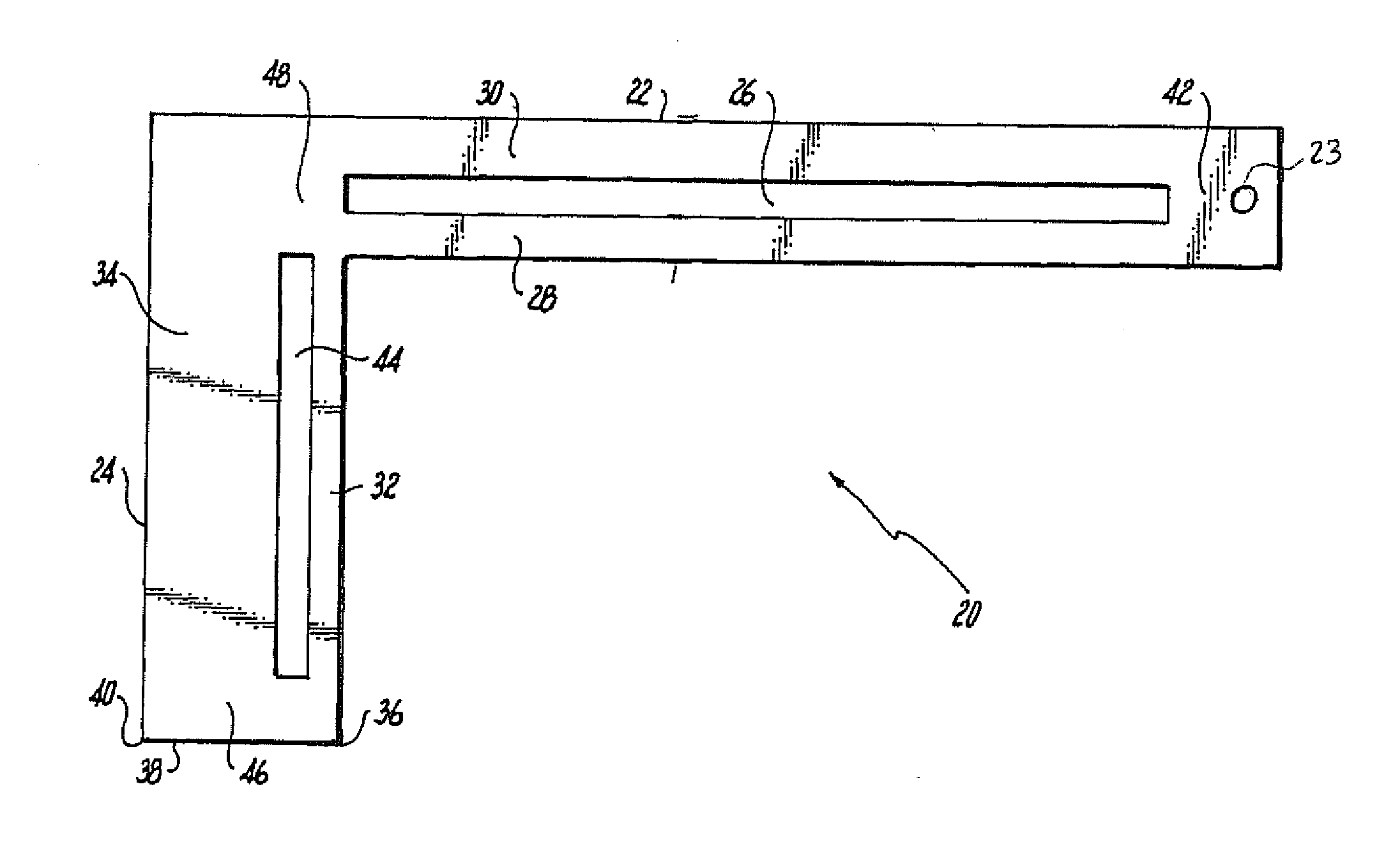
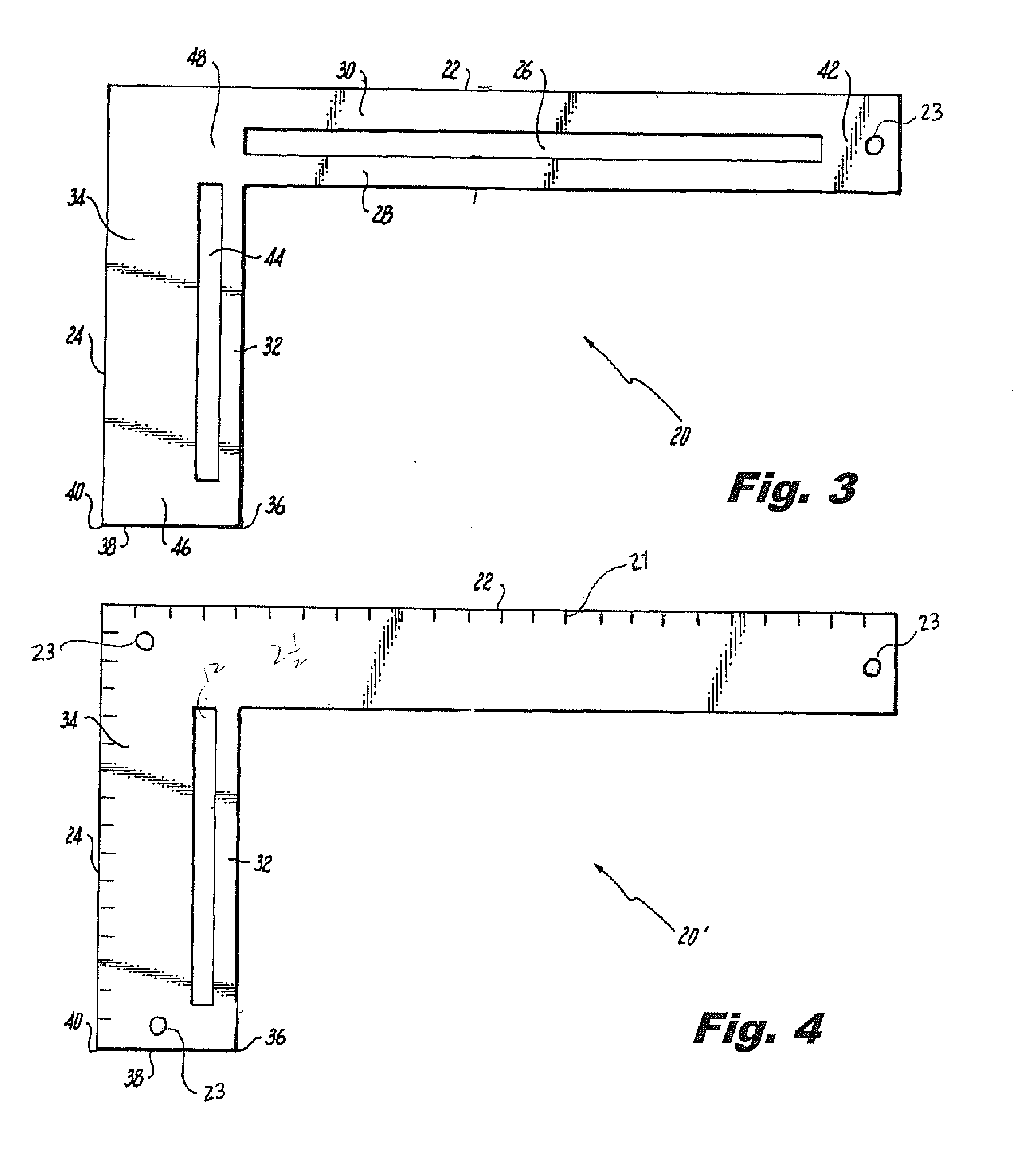
However, the use of the scales is somewhat cumbersome since the user must visually align the marks on the scale with the edge of the wall member.
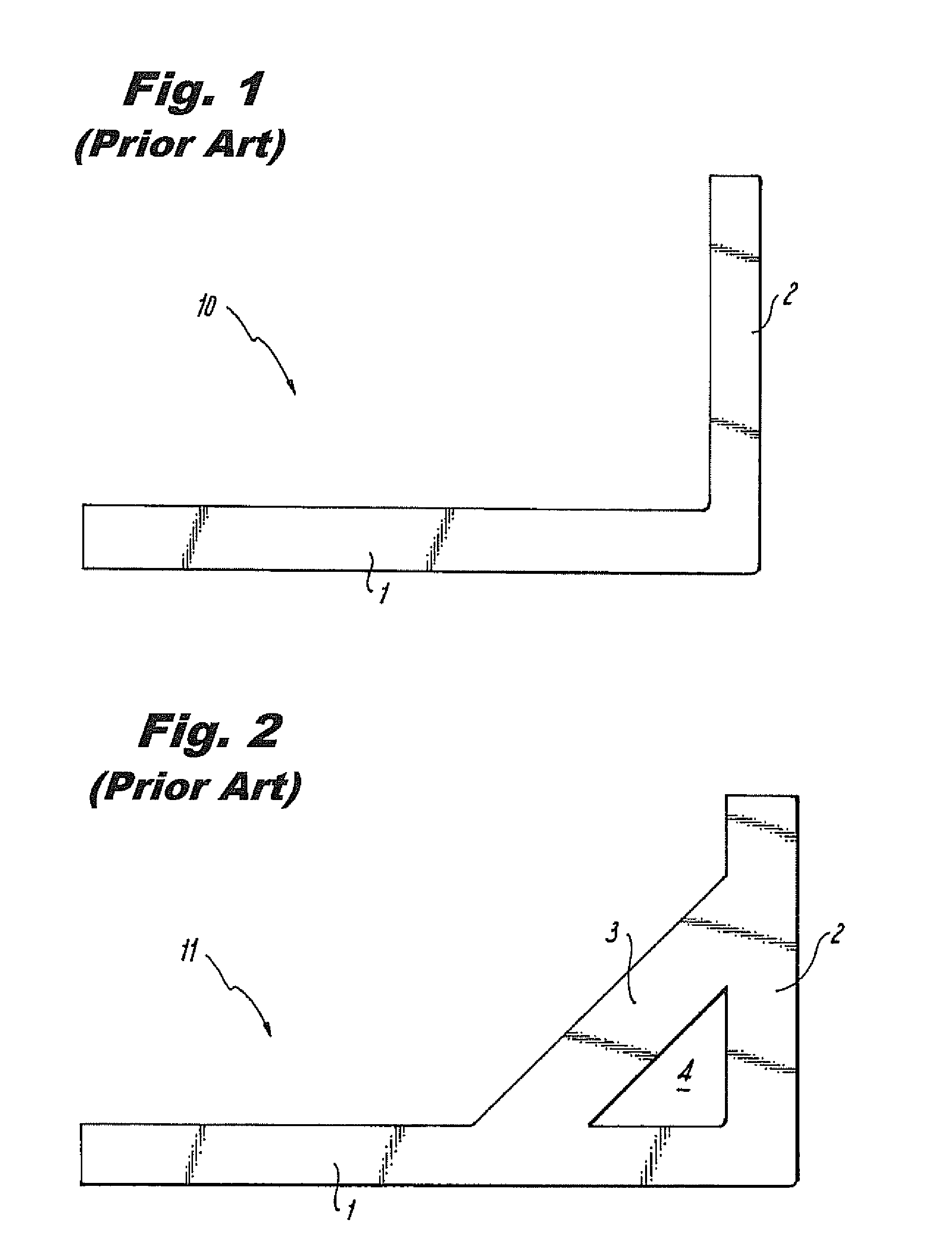
Such squares, and others, provide limited information and all require additional complex calculations to determine angles and lengths at which to cut framing members, especially those forming compound joinery.
In particular, these standard carpentry squares provide limited tabular information, and the measurement and alignment scales marked on the faces of these tools fail to address a large range of unequal pitches required during the design and building of unequal pitched roofs, for example.
Some squares comprise complicated hinge mechanisms in an effort to improve usability; these tools, however, are less reliably “square” and nonetheless still limited to the scant markings on the face of the body and tongue.
The combinations of materials create numerous possibilities for the wall thickness, and numerous potential errors.
Such a process requires a significant amount of measuring and movement of the framing square to complete, and must also be performed on both ends of every wall on the particular site.
Furthermore, in addition to the limited information provided to a builder or installer, existing squares are limited for use with either a standard measurement system (e.g., inches) or a metric system.
None are universally applicable to both standard and metric units of measurement.
Those squares that address metric systems are complex and cumbersome and require substantial additional calculations, which can result in computational errors and irreversibly incorrect cuts in framing members.

Method used


Image

  • Metal framing layout square and a method of using same
  • Metal framing layout square and a method of using same
  • Metal framing layout square and a method of using same

Examples


Embodiment Construction

[0048]As required, a detailed illustrative embodiment of the present invention is disclosed herein. However, techniques, systems, compositions and operating structures in accordance with the present invention may be embodied in a wide variety of sizes, shapes, forms and modes, some of which may be quite different from those in the disclosed embodiment. Consequently, the specific structural and functional details disclosed herein are merely representative, yet in that regard, they are deemed to afford the best embodiment for purposes of disclosure and to provide a basis for the claims herein which define the scope of the present invention.

[0049]Reference will now be made in detail to several embodiments of the invention that are illustrated in the accompanying drawings. Wherever possible, same or similar reference numerals are used in the drawings and the description to refer to the same or like parts or steps. The drawings are in simplified form and are not to precise scale. For pur...


PUM


Abstract

A metal framing layout square of substantially flat unitary construction and a method for using the same is provided. The square preferably includes an elongated blade, an elongated slot defined in the blade and parallel to the edges of the blade to provide two additional edges for the marking of measurement scales. The tool provides a tongue joined at a right angle to the blade. The metal framing layout square is preferably used with the layout phase of interior metal framed walls, and is directed to a metal framing layout square for use in constructing compound metal framing systems comprising a plurality of predetermined lengths and widths, and has slots which are to allow a user to readily mark a series of layout marks from a starting point to efficiently complete a set of markings for an entire framing structure with minimal need for secondary measuring devices.

Description

BACKGROUND OF THE INVENTION[0001]1. Field of the Invention[0002]The present invention relates generally to framing systems used in the construction of buildings, and tools for measurement and marking for metal framing systems that incorporate hollow metal tubing. More specifically, the invention relates to a metal framing layout square comprising a blade and tongue elements with one or both having an elongated slot therein for use in the layout phase of interior metal framed walls.[0003]2. Description of the Related Art[0004]There are many known framing systems used in the construction industry that are typically made of either wood or metal, with wood framing systems being the most common. As is well known, wood framing systems have enjoyed widespread use, and are typically constructed by connecting pieces of wood, such as 2×4's or 2×6's, with nails in a form that creates either the interior or exterior outline of a structure, or both. The major components are typically made of woo...

Claims


Application Information

Patent Timeline
Patent Type & Authority Applications(United States)
IPC IPC(8): G01B3/56G01B3/00G01B3/04
CPCG01B3/566G01B3/004G01B3/04B25H7/02
Inventor LAMANNA, MICHAELGROSS, RICHARD
Owner LAMANNA MICHAEL
Why Eureka
Try Eureka