This helps you quickly interpret patents by identifying the three key elements:
Problems solved by technology
Method used
Benefits of technology
Benefits of technology
The solution achieves simultaneous multi-region haptics with improved signal-to-noise ratio and reduced residual vibrations, providing clear and distinct tactile feedback at each sensing area even when multiple locations are touched simultaneously.
Problems solved by technology
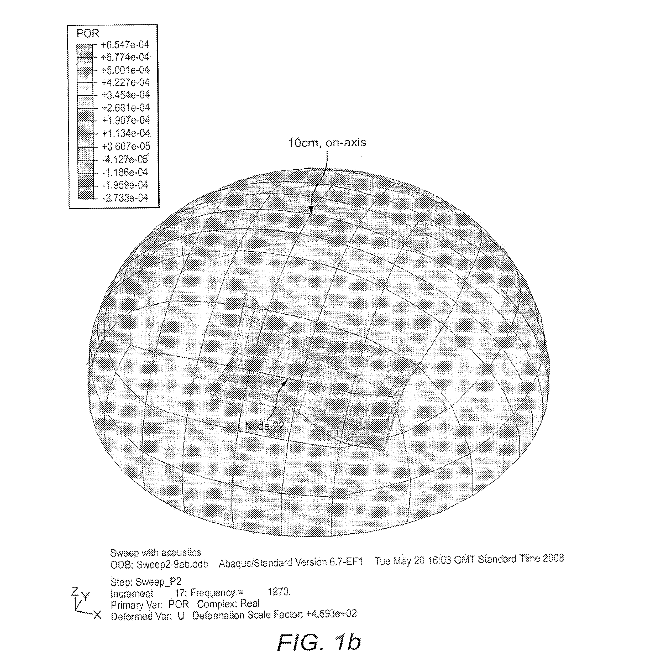
Anywhere else on the panel will experience a combination of the signals, but this is unimportant.
Method used
Image
Click on the blue label to locate the original text in one second.
Reading with bidirectional positioning of images and text.
Examples
example 1
m=3, n=2
[0195]Output 1 transfer admittances: P1—1=0.472+0.00344j
[0196]Output 2 transfer admittances: P1—2=−0.206−0.195j
[0197]Output 1 transfer admittances: P2—1=0.479−0.129j
[0198]Output 2 transfer admittances: P2—2=0.262+0.000274j
[0199]Output 1 transfer admittance: P3—1=−0.067−0.180j
[0200]Output 2 transfer admittance: P3—2=0.264+0.0014j
[0233]As V1 and V2 both correspond to a zero eigenvalue, a·V1+b·V2 is also an eigenve...
PUM
Abstract
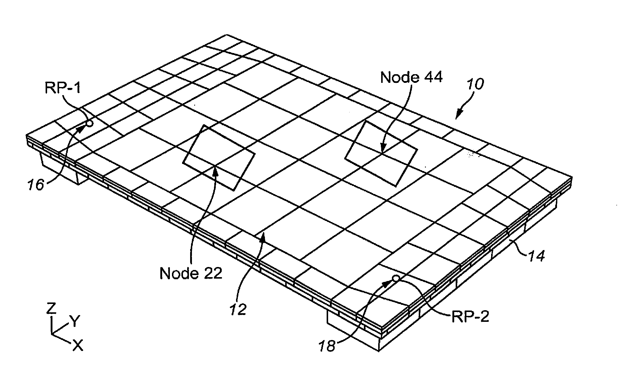
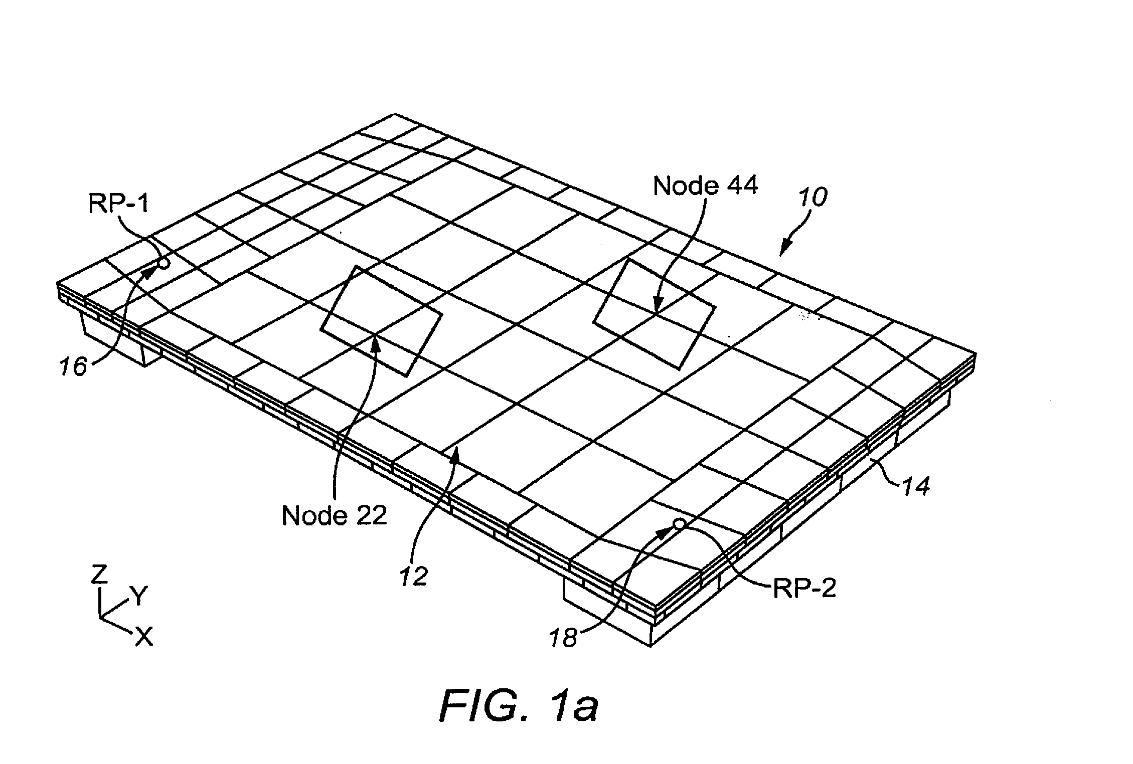
A touch sensitive device comprising a panel capable of supporting bending waves, a user-accessible touch sensitive screen on or forming part of a face of the panel, the touch sensitive screen having a plurality of different sensing areas, a plurality of vibration exciters coupled to the panel to apply bending waves to the panel to provide tactile feedback at the plurality of sensing areas in response to the user touching a sensing area, and signalprocessing means arranged to apply signals to the vibration exciters so as to steer bending waves applied to the panel by the plurality of vibration exciters whereby the amplitude of the applied bending waves is maximised at the sensing area touched by the user and reduced or minimised at each other sensing area.
Description
CROSS-REFERENCE TO RELATED APPLICATIONS[0001]This is a continuation application of U.S. patent application Ser. No. 12 / 921,935 filed Dec. 13, 2010 which is the U.S. National Phase of PCT Application No. JP2009 / 064365 filed 7 Aug. 2009 which claims priority to British Patent Application No. 0818117.4 filed 3 Oct. 2008, each of which are incorporated herein by reference.TECHNICAL FIELD[0002]The invention relates to touch sensitive devices including touch sensitive screens or panels.BACKGROUND ART[0003]U.S. Pat. No. 4,885,565, U.S. Pat. No. 5,638,060, U.S. Pat. No. 5,977,867, US2002 / 0075135 describe touch-operated apparatus having tactile feedback for a user when touched. In U.S. Pat. No. 4,885,565 an actuator is provided for imparting motion to the CRT when the actuator is energized to provide tactile feedback. In U.S. Pat. No. 5,638,060, a voltage is applied to a piezo-electric element which form a switch to vibrate the element to apply a reaction force to a user's finger. In U.S. Pa...
Claims
Application Information
Patent Timeline
Application Date:The date an application was filed.
Publication Date:The date a patent or application was officially published.
First Publication Date:The earliest publication date of a patent with the same application number.
Issue Date:Publication date of the patent grant document.
PCT Entry Date:The Entry date of PCT National Phase.
Estimated Expiry Date:The statutory expiry date of a patent right according to the Patent Law, and it is the longest term of protection that the patent right can achieve without the termination of the patent right due to other reasons(Term extension factor has been taken into account ).
Invalid Date:Actual expiry date is based on effective date or publication date of legal transaction data of invalid patent.
Patent Type & AuthorityApplications(United States)

