Ultrasound Surgical Micromotor

a micromotor and ultrasound technology, applied in the field of surgical handpieces, can solve the problems of inability to accurately detect the presence of tumors, inability to accurately detect tumors, and inability to effectively drill or cut, and achieve the effects of optimizing the adjustment of amplitude, optimizing the transmission of ultrasound vibration, and optimizing the adjustment of rotation speed

Inactive Publication Date: 2015-08-06
SOC POUR LA CONCEPTION DES APPL DES TECHN ELECTRONIQUES SATELEC
View PDF15 Cites 3 Cited by
  • Summary
  • Abstract
  • Description
  • Claims
  • Application Information

AI Technical Summary

Benefits of technology

[0022]Integrating rotary drive technology with ultrasound vibration technology makes it possible to offer effectiveness that is optimized in terms of cutting and / or drilling, for example. The operator can advantageously use a single handpiece for performing all of the treatments needed on the tissues concerned, thereby avoiding the need to pass from one appliance to another during the intervention.
[0023]Advantageously, the invention makes it possible both to optimize the adjustment of the amplitude of the ultrasound vibration, and to optimize the adjustment of the speed of rotation imparted by the rotary drive means either simultaneously or independently.
[0024]The invention also makes it possible to optimize the transmission of ultrasound vibration without disturbance due to the rotation, if any, of the rotary drive means.
[0025]By configuring the rotary drive means to move independently of the ultrasound piezoelectric transducer and by configuring the piezoelectric transducer to be static relative to the handpiece, the invention thus makes it possible to improve control over the ultrasound vibration generated by the piezoelectric transducer. Furthermore, the lifetime of the piezoelectric transducer is significantly increased thereby.

Problems solved by technology

That operating technique is relatively effective, but nevertheless involves certain risks, in particular because of the speed of rotation of the cutter which is sometimes difficult to control, and can thus lead to irreversible lesions of neighboring tissues such as a nerve or an artery.
Nevertheless, those technological solutions are not always satisfactory in terms of effectiveness in drilling or cutting.
The solution proposed in document U.S. Pat. No. 6,204,592 B1 nevertheless presents major drawbacks in terms in particular of the complexity of the structure of the handpiece.
The rotation and the vibration to which the insert is subjected are also relatively difficult to control when operating with that type of surgical handpiece.

Method used


Image

  • Ultrasound Surgical Micromotor
  • Ultrasound Surgical Micromotor
  • Ultrasound Surgical Micromotor

Examples


first embodiment

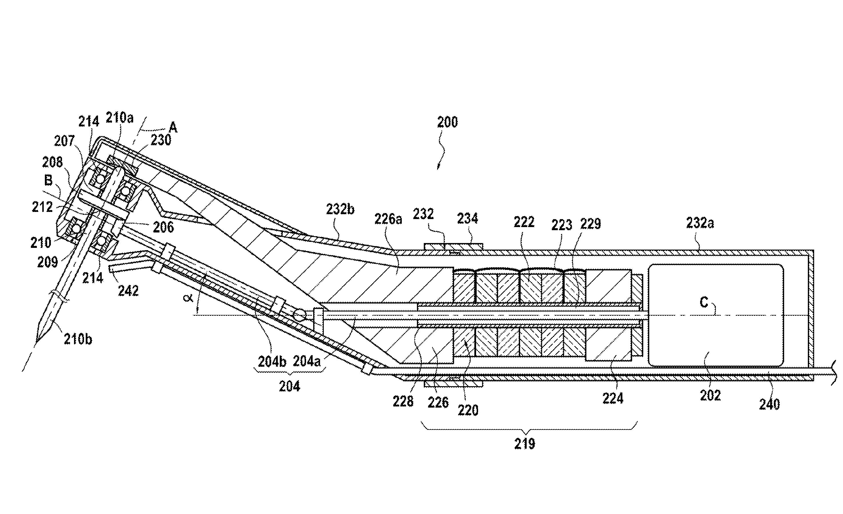
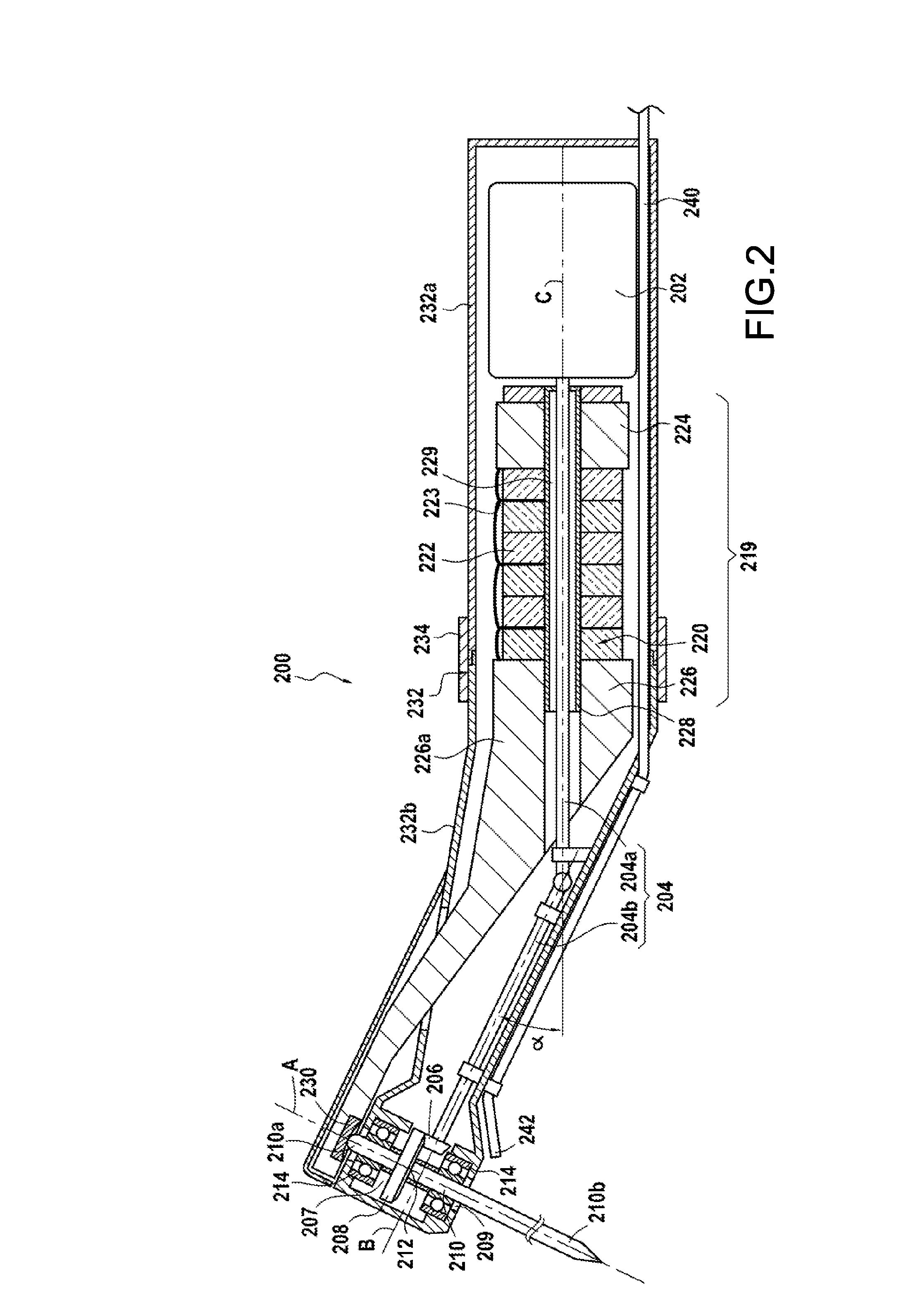
[0054]The surgical handpiece 200 in the invention is described below with reference to FIGS. 2, 3, 4A, and 4B.

[0055]More specifically, FIG. 2 is a diagrammatic lateral section view of the surgical handpiece 200. FIG. 3 is a plan view of the same handpiece 200.

[0056]The surgical handpiece 200 includes a micromotor 202 that is situated in the proximal portion of the handpiece. The micromotor 202 is mechanically coupled to the proximal portion 204a of a transmission shaft 204 that extends inside the body of the handpiece 202.

[0057]In this example, the transmission shaft 204 also includes a distal portion 204b that is mechanically coupled to the proximal portion 204a by a universal joint.

[0058]The distal portion 204b of the transmission shaft 204 in this particular example presents a non-zero angle α relative to the proximal portion 204a (angle between the axes of rotation B and C in FIG. 2). As described in greater detail below, this angle α may be zero in other embodiments of the inve...

second embodiment

[0103]A surgical handpiece 300 in the invention is described below with reference to FIG. 5.

[0104]Most of the components of the handpiece 300 are identical to the corresponding components of the handpiece 200 as described above. Unless otherwise specified, the components of the handpiece 300 present the same properties and perform the same operations as the corresponding components of the handpiece 200.

[0105]The ultrasound piezoelectric transducer 319 of the handpiece 300 comprises in particular a piezoelectric motor 320 arranged under pre-stress between a counterweight 324 and an amplifier portion 326, the distal portion of the amplifier portion being present in a housing 307. The elements 319, 320, 324, 326, and 307 are identical respectively to the elements 219, 220, 224, 226, and 207 of the handpiece 200.

[0106]The handpiece 300 differs from the handpiece 200 in that the rotary drive means operate by means of an air turbine and not by means of a micromotor.

[0107]More specifically...


PUM


Abstract

A surgical handpiece includes a housing for receiving an insert, and an ultrasound piezoelectric transducer having a piezoelectric motor placed between a counterweight and an amplifier portion. The piezoelectric transducer is suitable for transmitting ultrasound waves from a distal end of the amplifier portion. The distal end is present in the housing, and rotary drive means is present in the housing. The rotary drive means are movable independently of the ultrasound piezoelectric transducer, and the transducer is static relative to the handpiece.

Description

BACKGROUND OF THE INVENTION[0001]The present invention relates to surgical treatment appliances and, more particularly, to surgical handpieces for treating biological tissues (enamel, dentine, mucous membrane, bone, . . . ) or implanted prosthesis such as implants, prostheses, or any other active implantable device (heart valve, . . . ).[0002]The invention applies more particularly to cutting and / or drilling into biological tissues of various densities situated close to anatomical structures that are fragile and that need to be preserved, such as a membrane or a vital organ, for example.[0003]In conventional manner, for example when practicing osteotomy (e.g. cutting away bone from a knee), it is general practice to use a surgical handpiece provided with a micromotor driving a rotary cutter, the rotary motion of the cutter serving to dig into the bone tissue in highly effective manner. The same type of surgical handpiece is preferably used when it is desired to drill or alter a cavi...

Claims


Application Information

Patent Timeline
Patent Type & Authority Applications(United States)
IPC IPC(8): A61B17/32
CPCA61B17/1624A61B17/32002A61B17/320092A61C1/05A61C1/07A61B17/320068
Inventor DIERAS, FRANCISREGERE, PASCAL
Owner SOC POUR LA CONCEPTION DES APPL DES TECHN ELECTRONIQUES SATELEC
Why Eureka
Try Eureka