[0003]By contrast, the
electric machine according to the present invention, as well as the method according to the present invention for operating the same, have the
advantage that the number of conductor loops in the slots of the rotor is varied in such a way that the number of conductor loops of coils commutated one after the other yields a sine curve as a first approximation. Such a sinusoidal change in the number of conductor loops over the sequence in time of the commutation generates additional ripple in the motor current signal, whose frequency corresponds to the product of the
pole number, the number of periods of the sine function per commutating phase and the
rotational frequency of the
electric machine. This causes an additional ripple in the current characteristic to be produced, which is less in frequency than the slot frequency that is produced by the number of commutator segments. These additionally generated current peaks have an approximately constant amplitude, independently of the operational point of the electric
machine and the amount of the load current. This is why this superposed current ripple signal is able very favorably to be evaluated, in order to ascertain information about the rotational speed, or the
period duration of the rotor revolution. Because of the sinusoidal change of the conductor number over the commutation cycle, interferences of higher orders of the additional current ripple signal are largely able to be eliminated. Therefore,
noise excitations of the electric
machine, caused by the current ripple, may be greatly reduced, and so a relatively more quiet run may be achieved for convenience drives, in
spite of the
torque ripple.
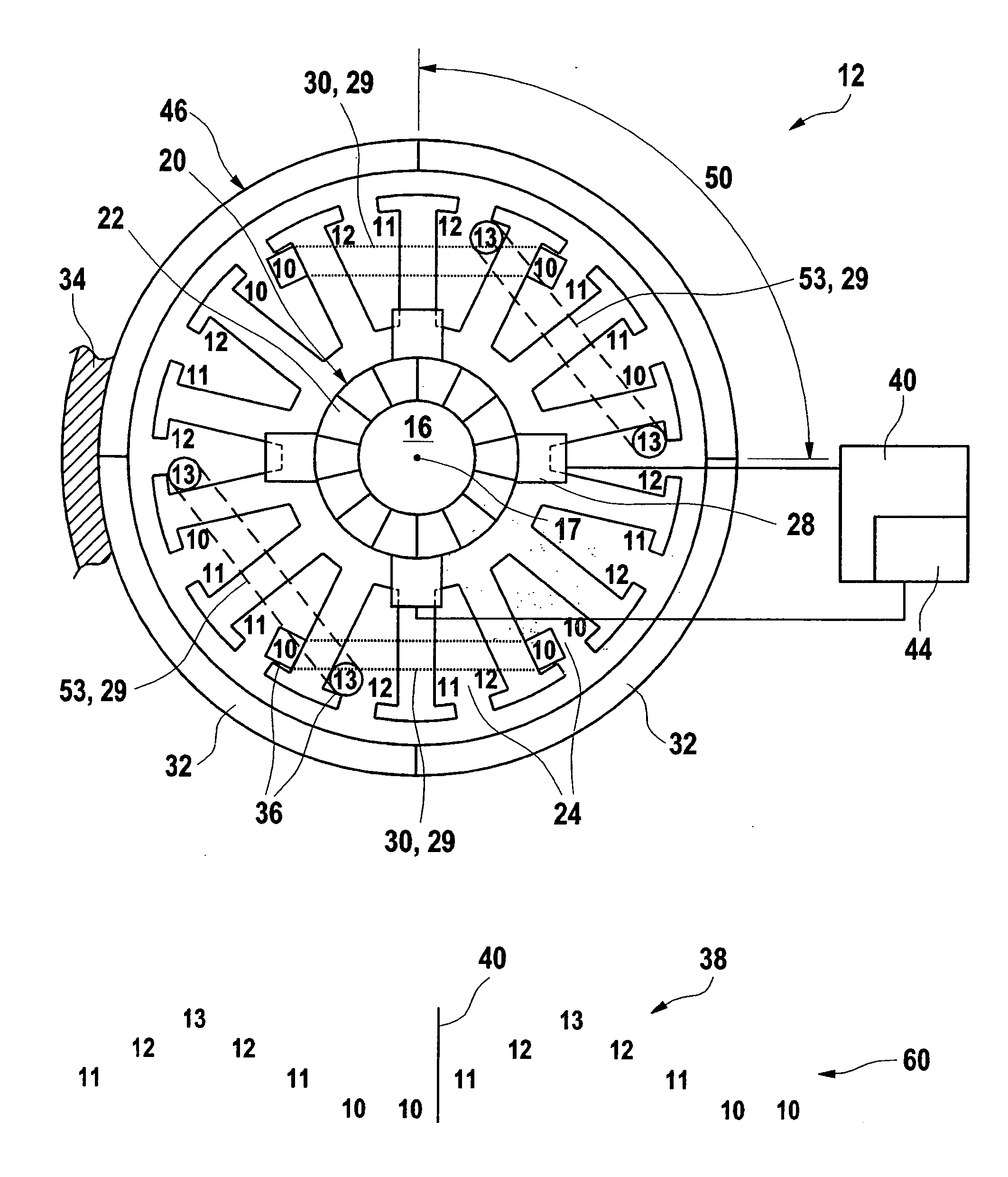
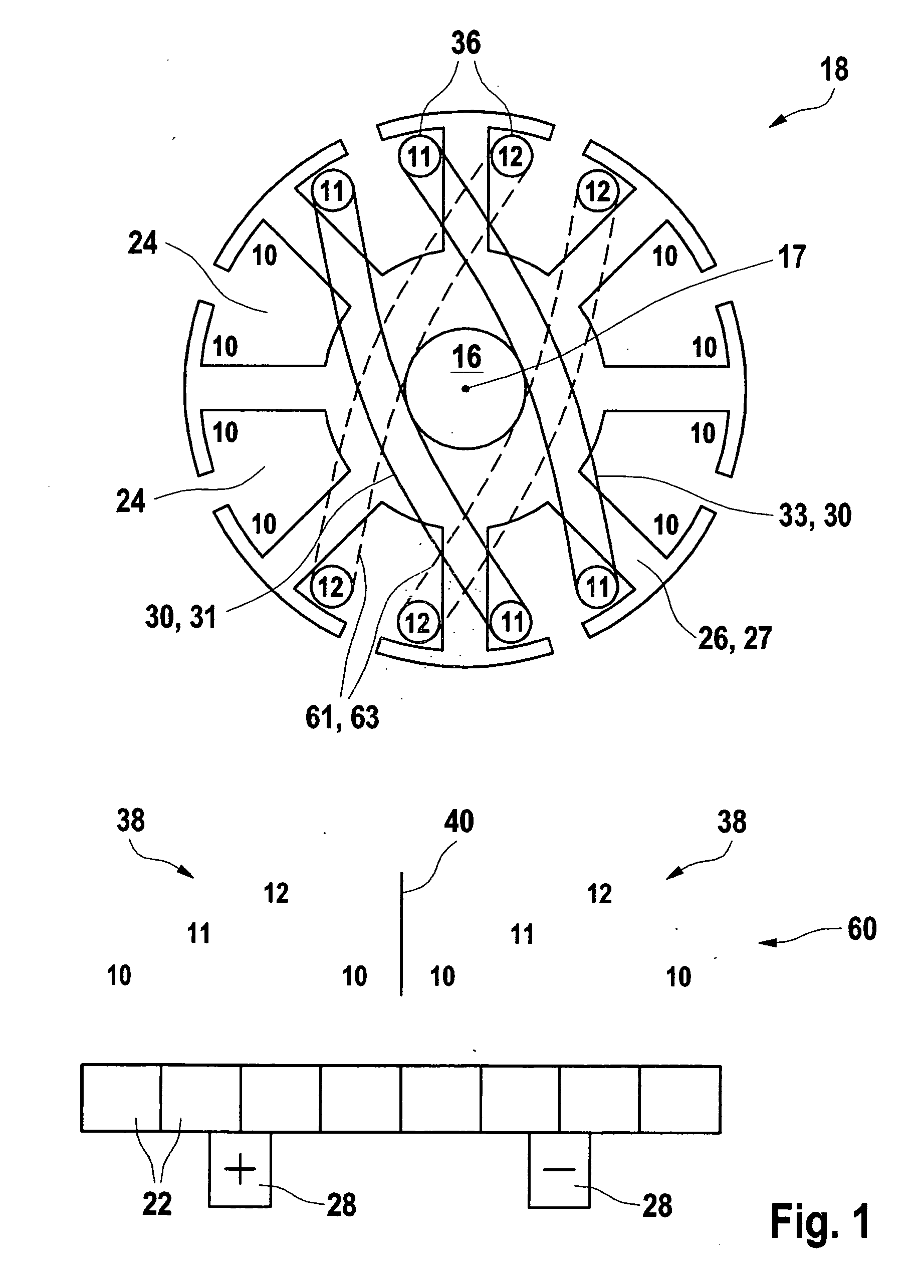
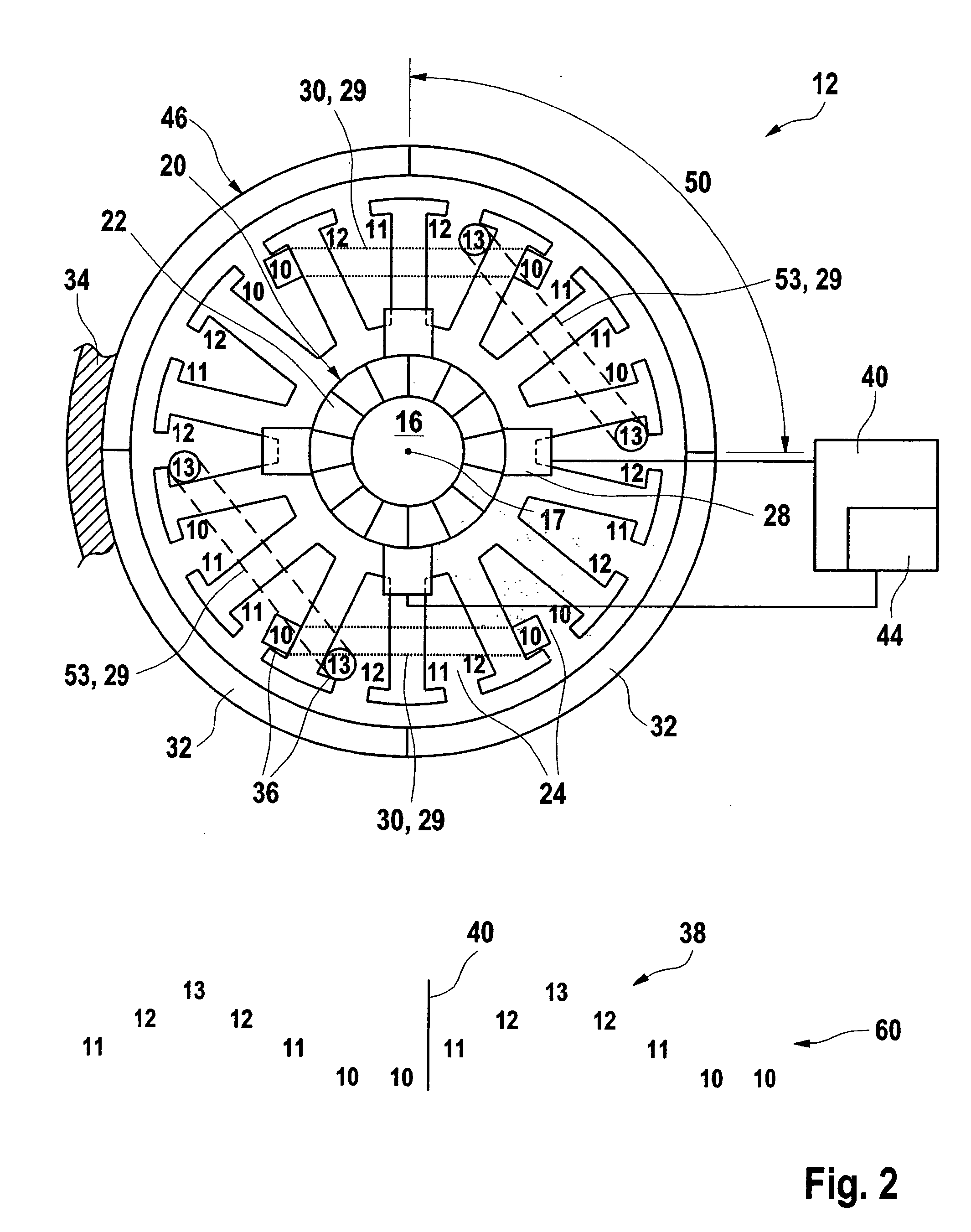
[0005]In one preferred embodiment, and electric
DC motor has a rotor having 14 slots, into which altogether also 14 coils are fitted. This embodiment has four
magnetic poles, for example, which are generated by a circumferential magnetic ring, which has a uniform pole ring
subdivision of preferably 90 degrees. In this embodiment, because of the sinusoidal change of the conductor loop number via the commutator cycle, and easy-to-detect ripple signal may be generated which, for instance, has
four current ripples per commutator revolution.
[0006]It is particularly favorable if the number of commutator segments, which preferably corresponds to the number of slots of the rotor, is not divisible by the number of the
magnetic poles. This reduces the
cogging torque of the electric machine and improves the
synchronism properties of the electric machine.
[0007]It is particularly favorable to develop exactly one period of the sine function over one commutation phase, using the change in the conductor loops per coil. The amplitude of the current ripple to be detected is thereby able to be maximized, whereby the evaluation device may be simplified.
[0011]The method according to the present invention, for operating an electric machine, preferably a
DC motor, has the
advantage that, because of the variation, according to the present invention, of the number of conductor loops of the individual coils, a uniform current ripple having relatively constant amplitude is able to be generated, which changes only insubstantially over various working ranges of the electric machine. Because of the clearly lower frequency of this additionally generated current ripple, the scanning frequency of the rotational speed evaluation unit is able to be reduced, whereby the requirements, and thus also the costs, of the evaluation device may be reduced. The ripple signal of the motor current, generated according to the present invention, may be used particularly favorably for implementing a jamming protection function of a motorically moved part. In this context, the signal representing the rotational speed is examined by the evaluation unit for a change with time, for which the time intervals between the individual current ripples are ascertained.

