Wireless data communication method via ultra-wide band encoded data signals, and receiver device for implementing the same

a data signal and ultra-wide band technology, applied in the direction of amplitude demodulation, line-fault/interference reduction, instruments, etc., can solve the problems of large electrical power consumption of the receiver device, the need to carry out correlation operations, and the use of information relative to the sign of pulses of ultra-wide band signals

Inactive Publication Date: 2010-12-07
ECOLE POLYTECHNIQUE FEDERALE DE LAUSANNE (EPFL)
View PDF23 Cites 4 Cited by
  • Summary
  • Abstract
  • Description
  • Claims
  • Application Information

AI Technical Summary

Benefits of technology

[0022]It is another object of the invention to provide a wireless data communication method via coded ultra-wide band data signals for maximising the amplitude of the data pulses in relation to the noise captured by the receiver device.

Problems solved by technology

Consequently, the electric power consumption of the receiver device is large, and many electronic components are necessary for processing signals in the receiver device, which constitutes a major drawback.
One drawback of this apparatus is that a correlation operation has to be carried out prior to demodulating and adding the pulses of the intermediate signals to retrieve the information.
Moreover, the shape of the pulses must be known, and only the direct path signals or one of the multiple path signals can be detected with this apparatus, which is a drawback.
One drawback of such a device is that the information relative to the sign of pulses of ultra-wide band signals has to be exclusively used.
A pulse energy maximisation in the set of sample from the addition directly is not carried out, which is another drawback.
One drawback of this device is that it is necessary to carry out correlation operations as soon as the UWB signals are received, which complicates the realisation of this device in the same way as for US Patent Application No. 2003 / 0095609.
Further, the communication system is limited to double pulse signals.
Consequently, the same drawbacks are observed as with the reception apparatus of the preceding Patent Application.

Method used


Image

  • Wireless data communication method via ultra-wide band encoded data signals, and receiver device for implementing the same
  • Wireless data communication method via ultra-wide band encoded data signals, and receiver device for implementing the same
  • Wireless data communication method via ultra-wide band encoded data signals, and receiver device for implementing the same

Examples


Embodiment Construction

[0050]In the following description, those elements of the wireless data communication system via ultra-wide band coded data signals used for implementing the communication method, which are well known to those skilled in the art, will not be explained in detail.

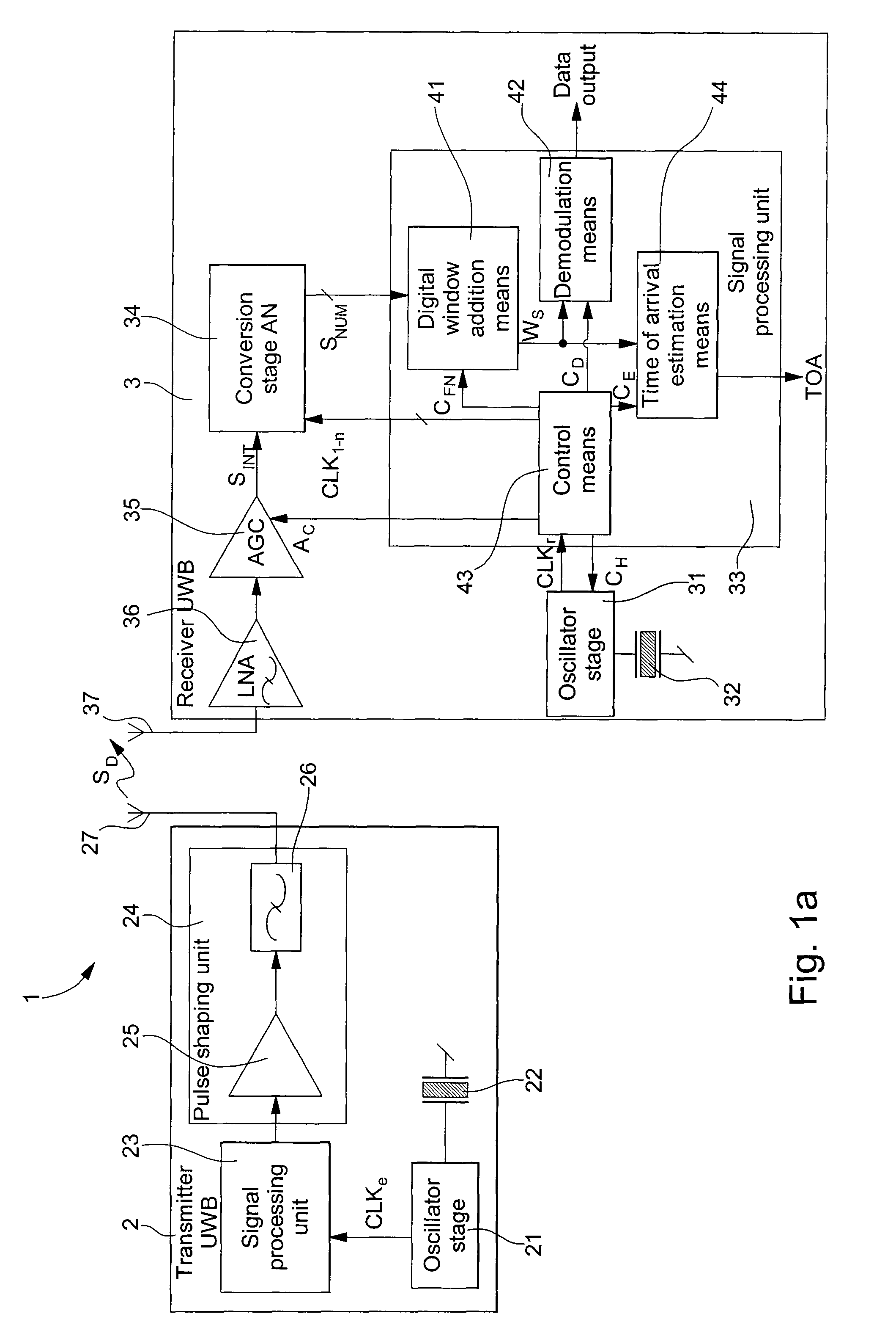
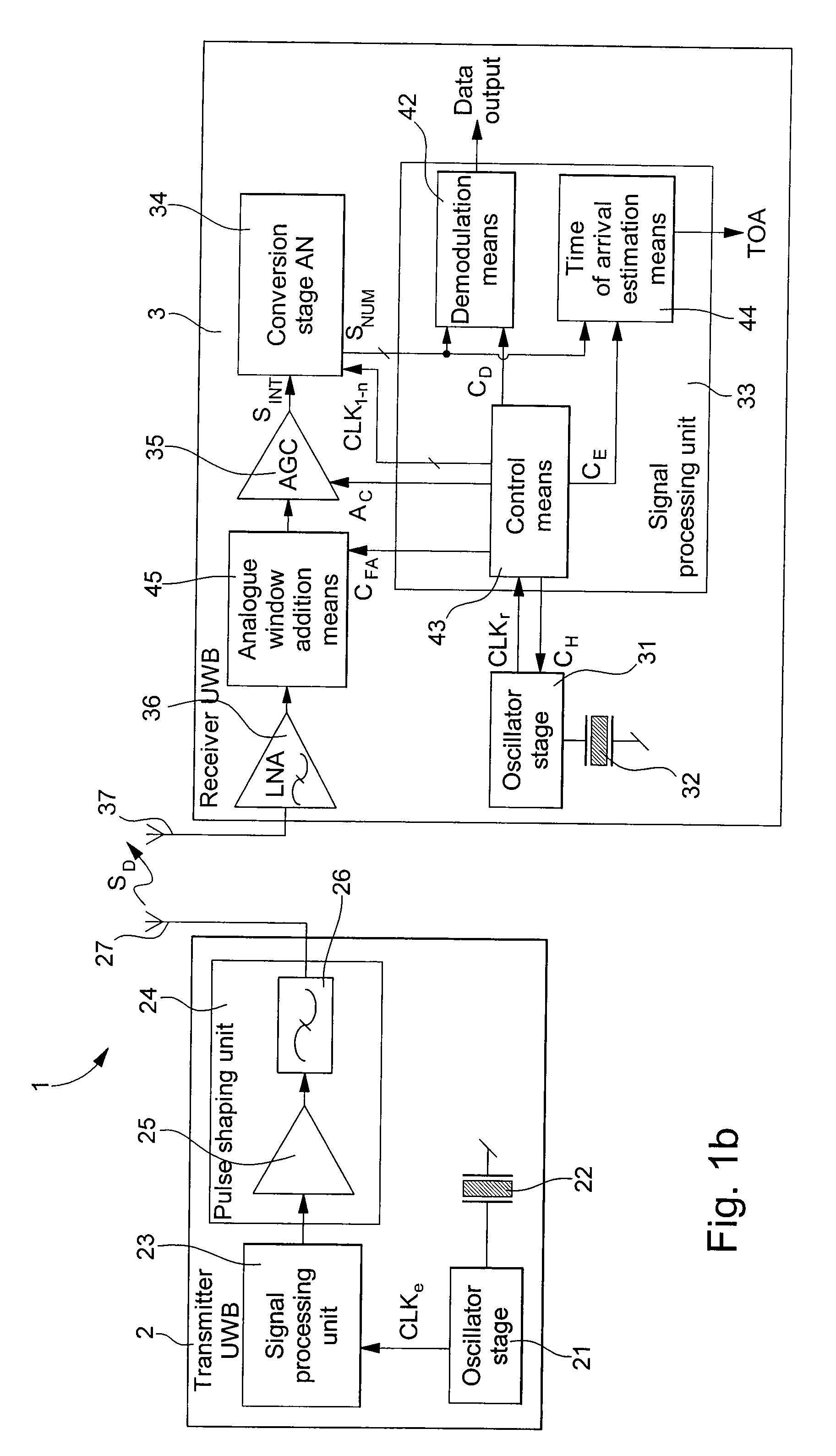
[0051]FIGS. 1a and 1b shows schematically a communication system 1 for implementing the wireless data communication method via ultra-wide band coded data signals SD. Communication system 1 includes at least one transmitter device 2, which transmits coded data signals SD via a first wide band antenna 27 and a receiver device 3, which receives direct path and / or multiple path coded data signals via a second wide band antenna 37.

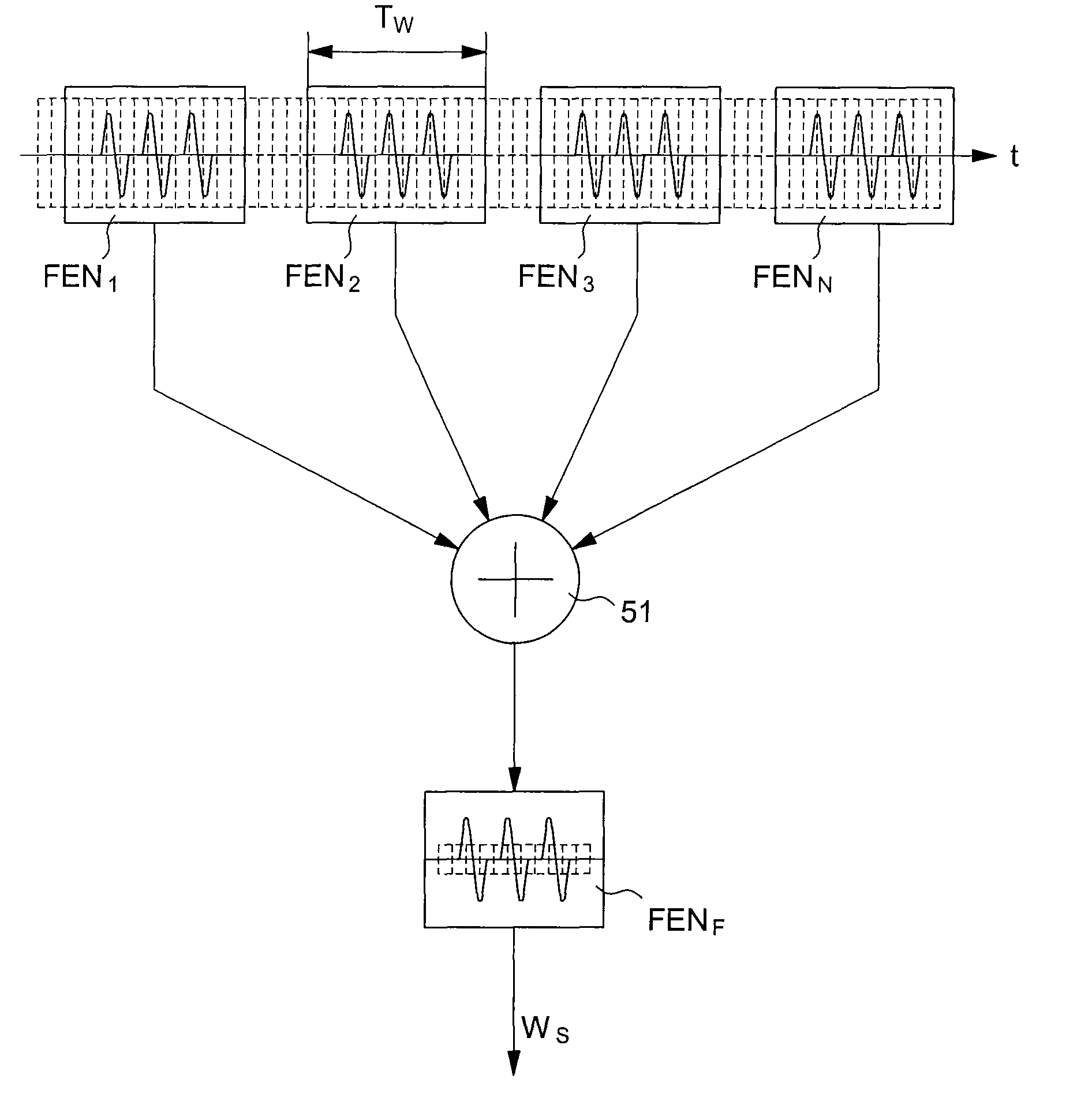
[0052]As explained hereinafter, particularly with reference to FIG. 2, the direct path and / or multiple path pulses received by receiver device 3 and corresponding to transmission of one of the N coded data signal pulses are processed or selected in one of the N corresponding time windows in receiver devi...


PUM


Abstract

This invention concerns a wireless data communication method, wherein a transmitter device having a first wide band antenna transmits ultra-wide band coded data signals to a receiver device having a second wide band antenna for receiving the direct and/or multiple path coded data signals. The transmitted data is defined by one or several sequences of N pulses where N is an integer number greater than 1. The arrangement of the N pulses of each sequence represents a data coding relative to the transmitter device. The N pulses of a sequence of direct and/or multiple path coded data signals received by the receiver device are processed each in one among N corresponding reception time windows. Each of the N reception time windows is positioned in time based on a known theoretic arrangement of the N pulses of signals transmitted by the transmitter device. An adding operation of the N windows is then performed in the receiver device so that the amplitude level of the constantly added pulses is higher than the amplitude level of the noise sensed by the receiver device.

Description

[0001]This is a National Phase Application in the United States of International Patent Application No. PCT / EP2004 / 014515 filed Dec. 21, 2004 which claims priority on European Patent Application No. 04000261.0, filed Jan. 8, 2004. The entire disclosures of the above patent applications are hereby incorporated by reference.FIELD OF THE INVENTION[0002]The present invention concerns a method for the wireless communication of data between a transmitter device and a receiver device. The transmitter device transmits ultra-wide band coded data signals via a first wide band antenna, and the receiver device receives direct and / or multiple path coded data signals via a second wide band antenna from the transmitter device. The transmitted data is defined by one or several successive sequences of N pulses where N is an integer number greater than 1. The arrangement of the N pulses of each sequence represents data coding relating to the transmitter device, i.e. identifying the transmitter device...

Claims


Application Information

Patent Timeline
Patent Type & Authority Patents(United States)
IPC IPC(8): H04B1/00G01S1/04G01S5/14H04B1/69H04L25/49
CPCH04B1/71632H04B1/71635H04B1/7183
Inventor MERZ, ROMANBOTTERON, CYRILFARINE, PIERRE-ANDRE
Owner ECOLE POLYTECHNIQUE FEDERALE DE LAUSANNE (EPFL)
Why Eureka
Try Eureka