

Monolithic ceramic capacitor and structure for mounting the same
- Summary
- Abstract
- Description
- Claims
- Application Information
AI Technical Summary
Benefits of technology
Problems solved by technology
Method used
Image

Examples
first embodiment
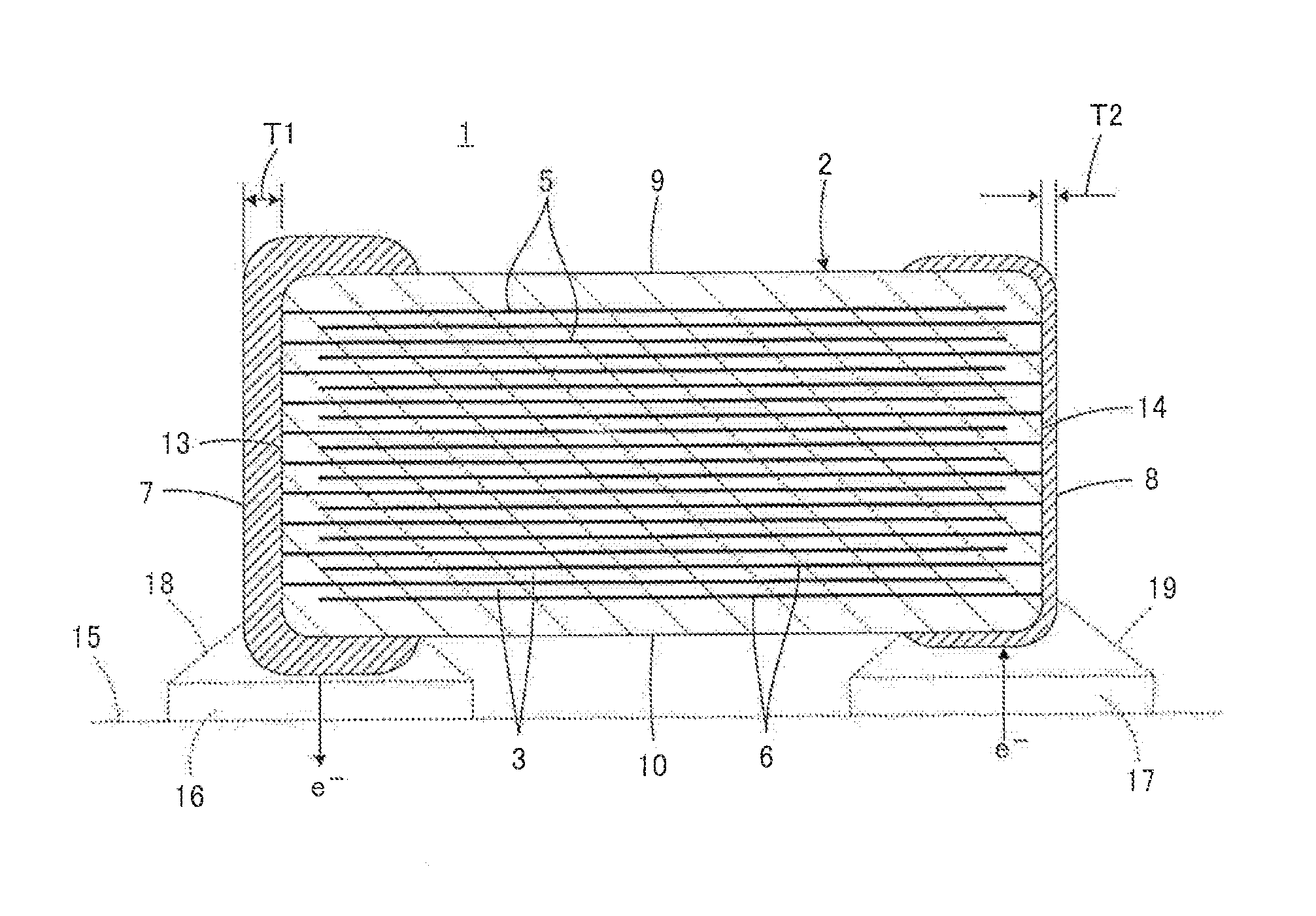
[0053]Referring to FIG. 1, a monolithic ceramic capacitor 1 according to the present invention will be described.
[0054]The monolithic ceramic capacitor 1 includes a multilayer body 2 which is a main body. The multilayer body 2 includes a plurality of dielectric ceramic layers 3 and inner electrodes (first inner electrodes 5 and second inner electrodes 6). The plurality of dielectric ceramic layers 3 are stacked on one another. Each of the inner electrodes is disposed along a corresponding one of a plurality of interfaces between the dielectric ceramic layers 3. A first outer electrode 7 and a second outer electrode 8 are respectively disposed at a first position and a second position on a surface of the multilayer body 2, the first and second positions being different positions, the surface of the multilayer body 2 being a surface that extends in a direction in which the dielectric ceramic layers 3 are stacked on one another.
[0055]More specifically, the multilayer body 2 has a subst...
second embodiment
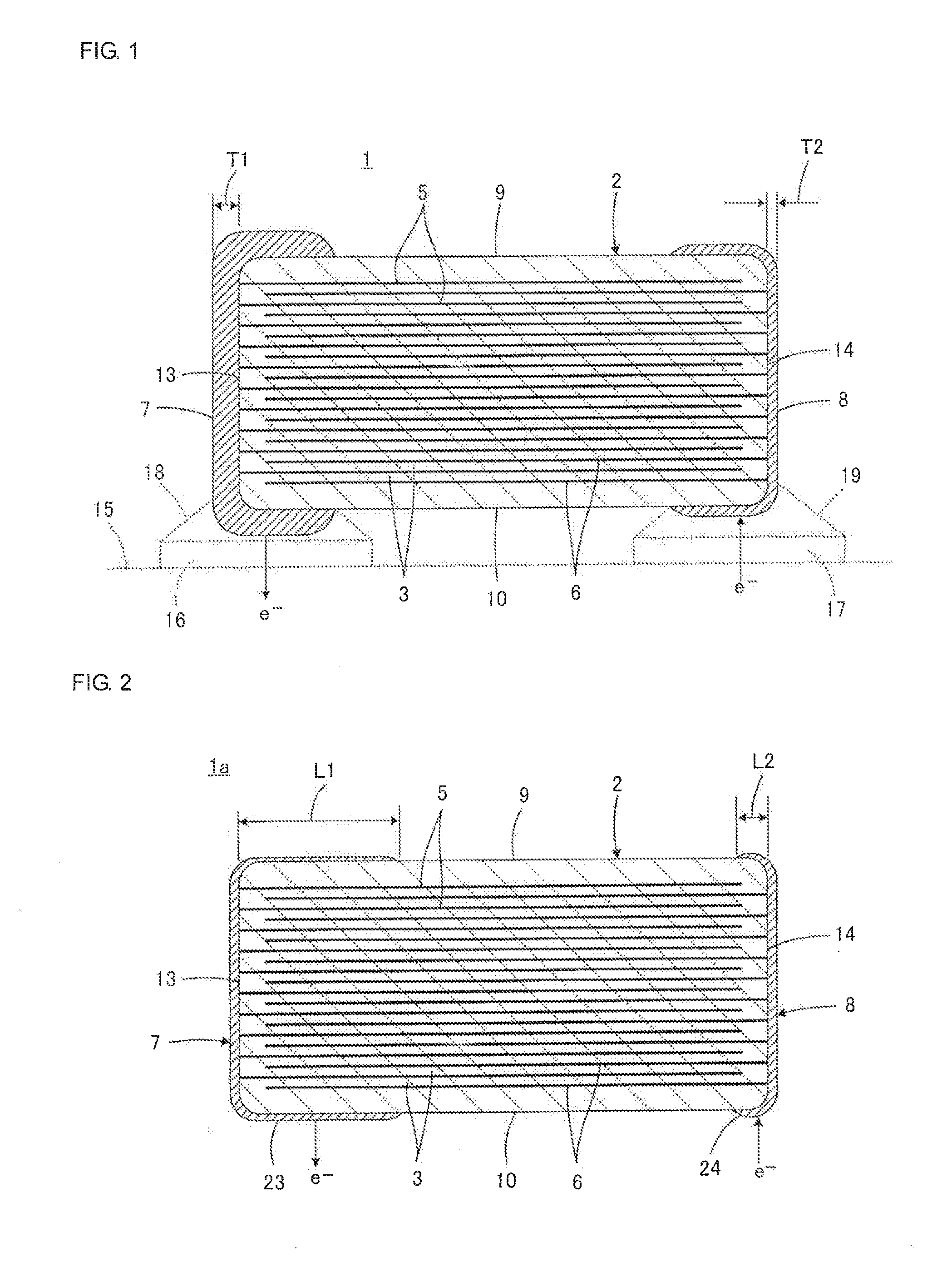
[0082]Referring to FIG. 2, a monolithic ceramic capacitor 1a according to the present invention will be described. In FIG. 2, components equivalent to the components illustrated in FIG. 1 are denoted by similar reference numerals so as to omit a duplicate description.
[0083]In the monolithic ceramic capacitor 1a, the first outer electrode 7 includes an adjacent-surface extending portion 23 that is formed so as to extend from the first end face 13 of the multilayer body 2 to the first and second principle surfaces 9 and 10 and the first and second side faces that are adjacent to the first end face 13. The second outer electrode 8 includes an adjacent-surface extending portion 24 that is formed so as to extend from the second end face 14 of the multilayer body 2 to the first and second principal faces 9 and 10 and the first and second side faces that are adjacent to the second end face 14. Note that the monolithic ceramic capacitor 1 described above also has this configuration.
[0084]Th...
third embodiment
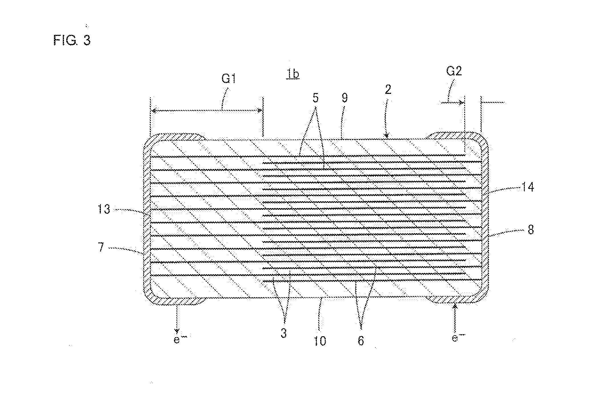
[0086]Referring to FIG. 3, a monolithic ceramic capacitor 1b according to the present invention will be described. In FIG. 3, components equivalent to the components illustrated in FIG. 1 are denoted by similar reference numerals so as to omit a duplicate description.
[0087]In the monolithic ceramic capacitor 1b, the first end face 13 and the second inner electrodes 6 are disposed with a first length-direction gap G1 interposed therebetween. The second end face 14 and the first inner electrodes 5 are disposed with a second length-direction gap G2 interposed therebetween. The monolithic ceramic capacitor 1 described above also has this configuration.
[0088]The third embodiment has a feature in which the first length-direction gap G1 is greater than the second length-direction gap G2. This feature implements a moisture-resistance reliability improving means. That is, by making the first length-direction gap G1 greater than the second length-direction gap G2, it is possible to increase a...
PUM
| Property | Measurement | Unit |
|---|---|---|
| Thickness | aaaaa | aaaaa |
| Thickness | aaaaa | aaaaa |
| Water vapor transmission rate | aaaaa | aaaaa |
Abstract
Description
Claims
Application Information