Decoy keel for automatic motion

Inactive Publication Date: 2015-10-08
MINTZ DONALD
7 Cites 2 Cited by

AI-Extracted Technical Summary

Problems solved by technology

Decoy behavioral matching is one of the most important factors in creating visible signals to attract live waterfowl, however efficiently and cost effective incorporation of characteristic movements and behaviors into conventional decoys has proven to be a challenge on many levels.
Manual intervention by the hunter to produce motion in the decoys, such as by pulling a rope attached to a group of decoys, can also draw attention to the hunter and frighten live waterfowl when the hunter's movements become visible.
The requirement for manual int...

Benefits of technology

[0022]Further, the location on the ventral surface of the waterfowl decoy to which the keel is affixed contributes to the directionality of decoy movement. In operation, a hunter may deploy multiple decoys at a time to simulate the behavioral characteristics of a flock of waterfowl residing in a specific body of water. To produce substantially random movements within the waterfowl decoy flock, the keel size, shape and attachment location may be varied on individual decoys to produce a random pattern of movement which will be observed as natural by passing waterfowl. In one example, placing the leading edge of the keel on the ventral surface of the waterfowl decoy from approximately 1 inch to 5 inches and preferably 3.5 inches from the front of the chest or forward facing region creates an oscillatory motion when the decoy is deployed into a moving body of water such as a river. Modifying the distance the keel is located from the chest portion can change the degree to which a decoy will oscillate, for example, when placed in a moving body of water.
[0023]The shape and symmetry of the decoy in addition to the placement symmetry of the keel on the ventral surface of the decoy will determine t...

Abstract

A waterfowl decoy having a keel for the production of automatic motion is provided. The waterfowl decoy comprises a body, a chest or forward facing region, a tail or rearward facing region, a ventral surface or downward facing region, and a keel affixed to the ventral surface of the waterfowl decoy. When submerged in water, Bernoulli forces act on the keel translating to the ventral surface and generating automatic motion in the waterfowl decoy.

Application Domain

Animal huntingPropulsive elements of non-rotary type +2

Technology Topic

EngineeringDecoy +1

Image

  • Decoy keel for automatic motion
  • Decoy keel for automatic motion
  • Decoy keel for automatic motion

Examples

  • Experimental program(1)

Example

[0040]In the following detailed description, reference is made to the accompanying drawings that form a part hereof and in which are shown, by way of illustration, specific embodiments. In the drawings, like numerals describe substantially similar components throughout the several views. Other embodiments may be utilized and structural or logical, changes may be made without departing from the scope of the present disclosure. The following detailed description is, therefore, not to be taken in a limiting sense.
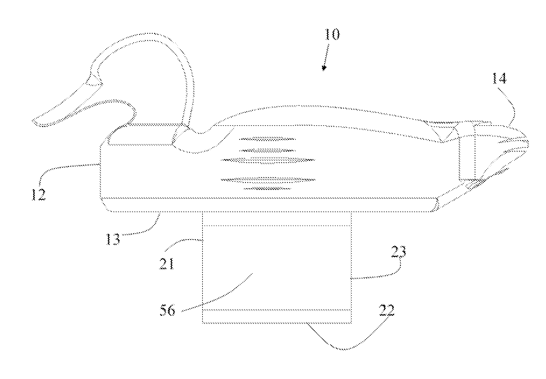
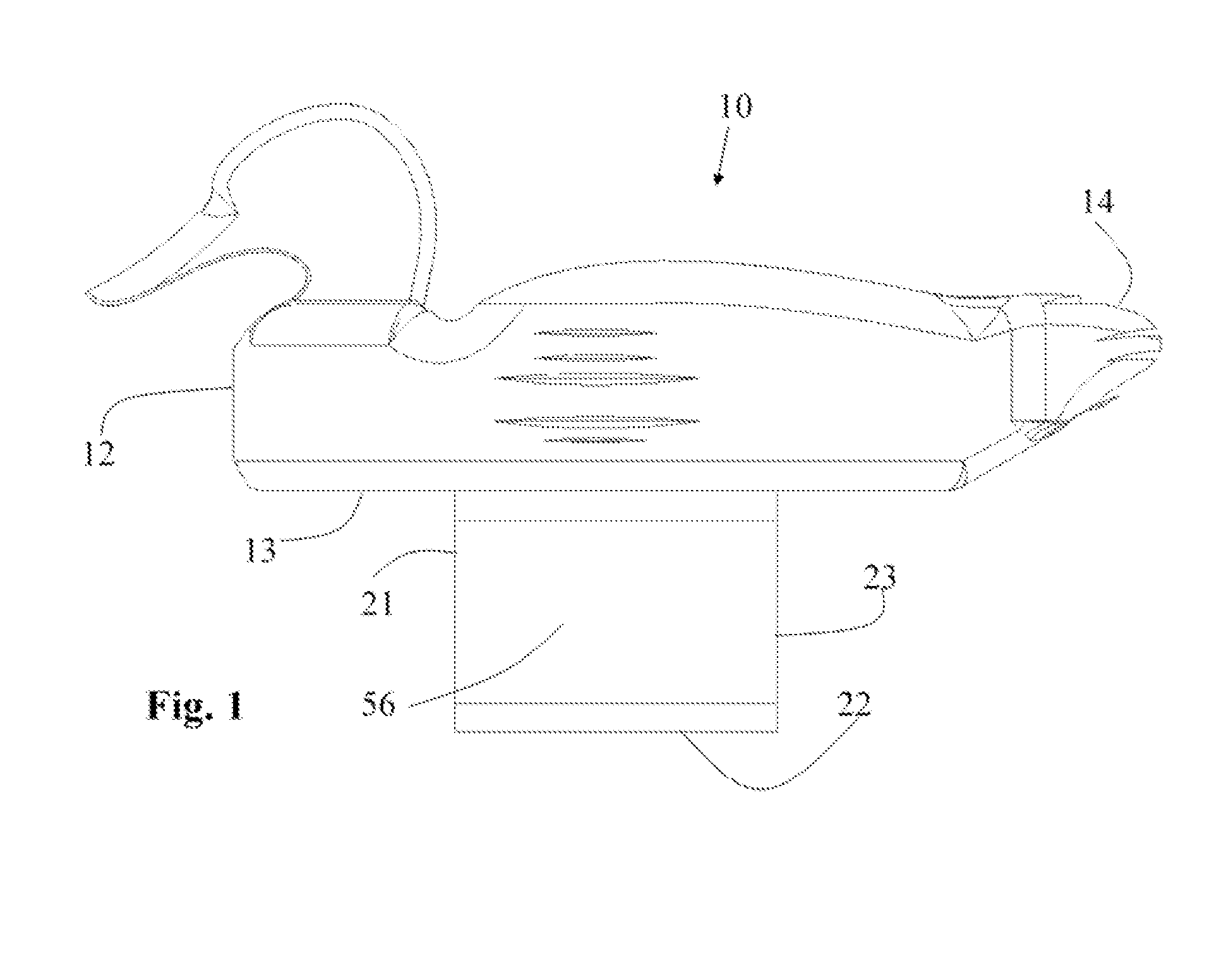
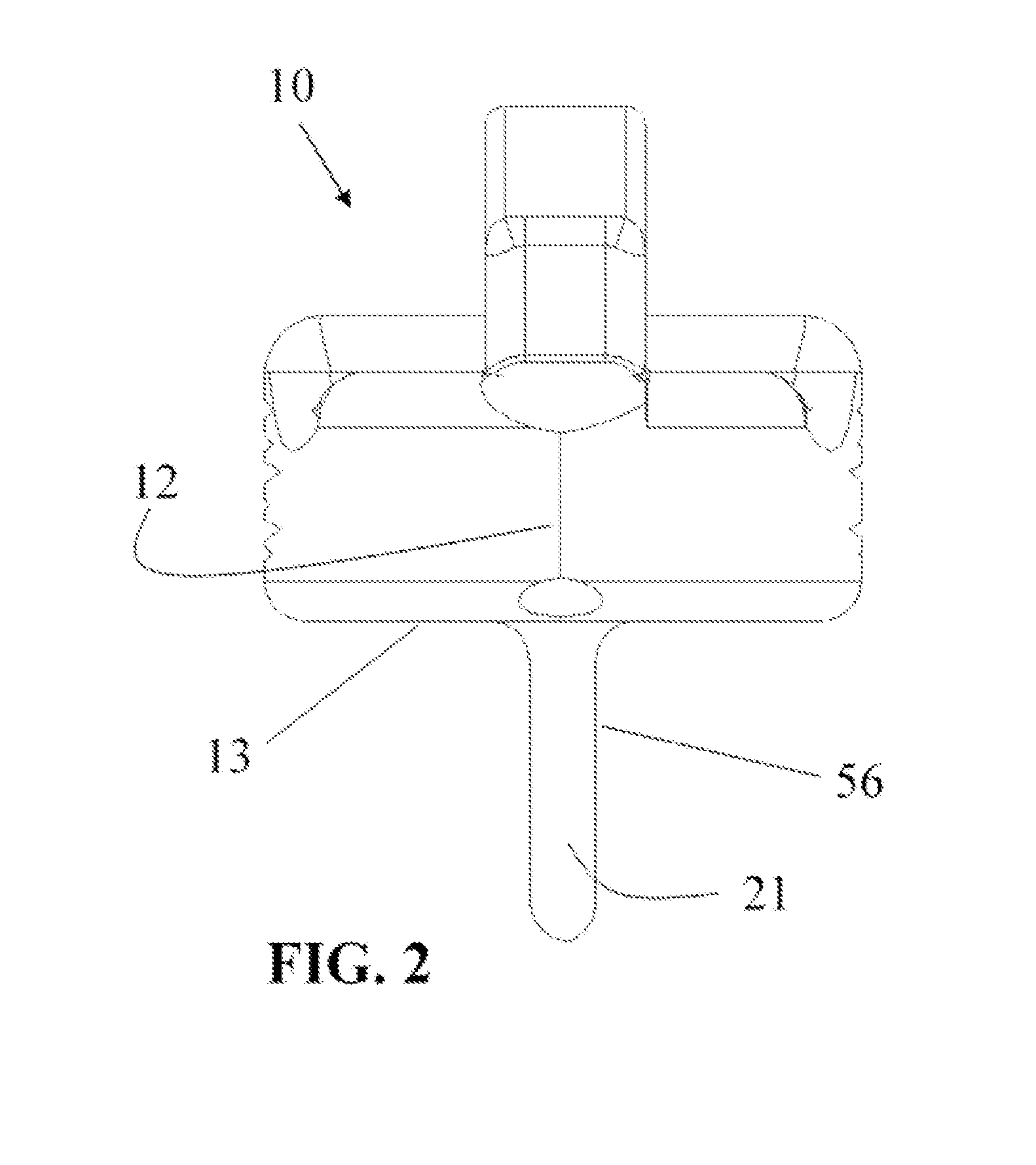
[0041]Referring to the drawings, and initially to FIG. 1, a waterfowl decoy 10 in accordance with the present invention comprises a body having a chest or forward facing region 12, a tail or rearward facing region 14, a ventral surface or downward facing region 13, a keel 56 affixed to said ventral surface or downward facing region 13, said keel having a leading edge 21, a trailing edge 23, and a connecting edge 22. In a preferred embodiment, the leading edge 21 of the keel is affixed to the ventral surface 13 of the waterfowl decoy in a region of the ventral surface adjacent the chest or forward facing region 13 and preferably at a distance from 1 to 7 inches.
[0042]Connecting edge 22 adjoins the leading edge 21 and trailing edge 23, preferably in a straight line. In a preferred embodiment, the connecting edge 22 is located at a depth from 1 to 8 inches from the ventral surface 13. Modulation of the depth of the connecting edge 22 provides a means of increasing the surface area of the keel 56 so as to control the magnitude of decoy movements produced by Bernoulli forces or turbulence within a body of water acting on the keel 56. A further means of modulating the surface area of the keel 56 by extending the distance between the leading edge 21 and the trailing edge 23 so as to increase the surface area on which Bernoulli forces act. Increasing the overall surface area of the keel 56 provides larger waterfowl decoy movements under a given force, whereas a reduction in surface area will produce relatively smaller movements. In a preferred embodiment, the ventral surface of the waterfowl decoy 10 has a length to width ratio of approximately 15:8 and provides a keel 56 having a surface area of approximately 12 square inches. In the preferred embodiment described, the connecting edge 22 has a length of approximately 3 inches and the leading edge 21 has a length of approximately 4 inches.
[0043]FIG. 2 is a front view of the waterfowl decoy showing a chest or forward facing region 12, a leading edge 21 of the keel 56 positioned in a preferred embodiment on a midline of the waterfowl decoy 10 to create a substantially symmetrical configuration. The symmetrical configuration by placement of the keel 56 along a midline of the waterfowl decoy allows for the generation of substantially symmetrical movements. However, it is noted that to create dissimilar movements within a group of decoys, the keel 56 placement, location, orientation, size and configuration can be substantially varied for individual waterfowl decoys without departing from the scope of the invention. Similarly, the chest or forward facing region 12 can be varied in shape to create either symmetrical or non-symmetrical movements. For example, for the production of symmetrical movements, the chest or forward facing region 12 contacting water is preferably rounded or arc shaped. The keel 56 is perpendicularly oriented to the ventral surface 13 of the waterfowl decoy 10 but can also be varied for individual waterfowl decoys to produce substantially dissimilar movements within a group of decoys. For example, the keel 56 may be affixed to the ventral surface 13 of the waterfowl decoy 10 in a non-perpendicular fashion so as to create non-symmetrical movements. A group of waterfowl decoys may have keels 56 at various angles relative to their respective ventral surfaces13 so as to produce substantially random movements within the group of waterfowl decoys.
[0044]FIG. 3 is a bottom view showing the ventral surface 13 of the waterfowl decoy 10, a keel 56 is affixed to the ventral surface 13 by a leading edge 21, an a trailing edge 23, having a connecting edge 22 adjoining, the leading edge 21 and the trailing edge 23. In a preferred embodiment, the leading edge 21 is aligned with the trailing edge 23 along a midline of the waterfowl decoy.
[0045]FIG. 4 shows a perspective view of a waterfowl decoy 10 having a chest or forward facing region 12 and a ventral surface or downward facing region 13 in which a keel 56 having a leading edge 21 and a connecting edge 22, said keel comprising a hinge 33 for the purpose of allowing the keel 56 to be oriented at various angles when deployed in water so as to create non-symmetrical movements if such movements are desired by the hunter. A keel oriented perpendicular to the ventral surface 13 of the decoy allows for the creation of symmetrical movements when placed in a body of water. Further, the hinge 33 enables the keel to be folded against the ventral surface 13 of the waterfowl decoy 10 for the purpose of packaging or transport of the waterfowl decoy so as to reduce the volume of the transport container or package required.
[0046]FIG. 5 is a perspective view of the ventral surface 13 of the waterfowl decoy 10 having a chest or forward facing region 12 and a keel 56 having a leading edge 21 and a connecting edge 22, said keel comprising a hinge 33 in which the keel 56 has been folded against the ventral surface 13 of the waterfowl decoy 10. A folded keel position allows for easier transport and volume reduction of associated containers or packaging. In addition, a folded keel enables the hunter to create variations in movement within a group of waterfowl decoys. For example, the keel 56 that is oriented parallel to the ventral surface 13 of the waterfowl decoy would substantially reduce Bernoulli forces created on the keel and limit or eliminate decoy movements. A keel 56 angled with respect to the ventral surface but not perpendicular would allow for the creation of asymmetrical movements.
[0047]FIG. 6 is a perspective view of a waterfowl decoy 10 having a chest or forward facing region 12 a ventral surface or downward facing region 13 and a keel 56 having a leading edge 21 and a connecting edge 22. The keel 56 is shown to be disconnected from the attachment to the waterfowl decoy. The waterfowl decoy 10 comprises a means of attaching a keel 35 located on the ventral surface or downward facing region 13 of the waterfowl decoy. Similarly, the detached keel 56 comprises a complimentary structure 34 in which the keel 56 may be engaged to the waterfowl decoy using the means for attaching a keel 35. In one example, the keel 56 is removably attached to the ventral surface 13 of the waterfowl decoy using a means for attaching the keel 35. The ability to detach the keel from the waterfowl decoy allows for more efficient packaging and transport and offers the hunter an option for controlling motion within an individual decoy or group of decoys. Further, the means for attaching the keel 35 may provide additional functionality to the keel. In one example, the means for attaching a keel includes a hinge structure which enables attachment and detachment of the keel to the decoy in addition to rotation about an axis of the means for attaching the keel 35 for the purpose of folding the keel against the ventral surface of the waterfowl decoy.
[0048]FIG. 7 is a perspective view of a waterfowl decoy 10 having a chest or forward facing region 12 a ventral surface or downward facing region 13 and a keel 56 having a leading edge 21 and a connecting edge 22. The keel 56 further comprises a weighted region 74 in which the center of gravity of the waterfowl decoy 10 is lowered so as to orient the waterfowl decoy in a upright position when placed in water. Adding a weight to the keel allows a hunter to deploy the decoy into a body of water in an upright position.
[0049]In one example, the keel is formed of a material having a weight and density suitable for lowering the center of gravity of the waterfowl decoy.
[0050]In one example, a region of the keel adjacent a connecting edge 22 is formed of a material has a weight and density suitable for lowering the center of gravity of the waterfowl decoy.
[0051]In one example, material from a region of the keel adjacent a connecting edge is removed and replaced with a material of suitable weight and density for lowering the center of gravity of the waterfowl decoy.
[0052]Although specific embodiments have been illustrated and described herein, it will be appreciated by those of ordinary skill in the art that any arrangement that is calculated to achieve the same purpose may be substituted for the specific embodiments shown. Many adaptations will be apparent to those of ordinary skill in the art. Accordingly, this application is intended to cover any adaptations or variations.

PUM

no PUM

Description & Claims & Application Information

We can also present the details of the Description, Claims and Application information to help users get a comprehensive understanding of the technical details of the patent, such as background art, summary of invention, brief description of drawings, description of embodiments, and other original content. On the other hand, users can also determine the specific scope of protection of the technology through the list of claims; as well as understand the changes in the life cycle of the technology with the presentation of the patent timeline. Login to view more.
Why Eureka
Try Eureka