Management & control of a sealing element of a rotating control device

Active Publication Date: 2015-10-08
SCHLUMBERGER TECH CORP
View PDF3 Cites 10 Cited by
  • Summary
  • Abstract
  • Description
  • Claims
  • Application Information

AI Technical Summary

Benefits of technology

[0004]Embodiments of the present invention serve to provide methods and systems to improve tolerance of misalignment between the shaft aligned with the managed pressure drilling operation equipment of an oil rig and the RCD and BOP aligned with the well head. Embodiments of the invention furt

Problems solved by technology

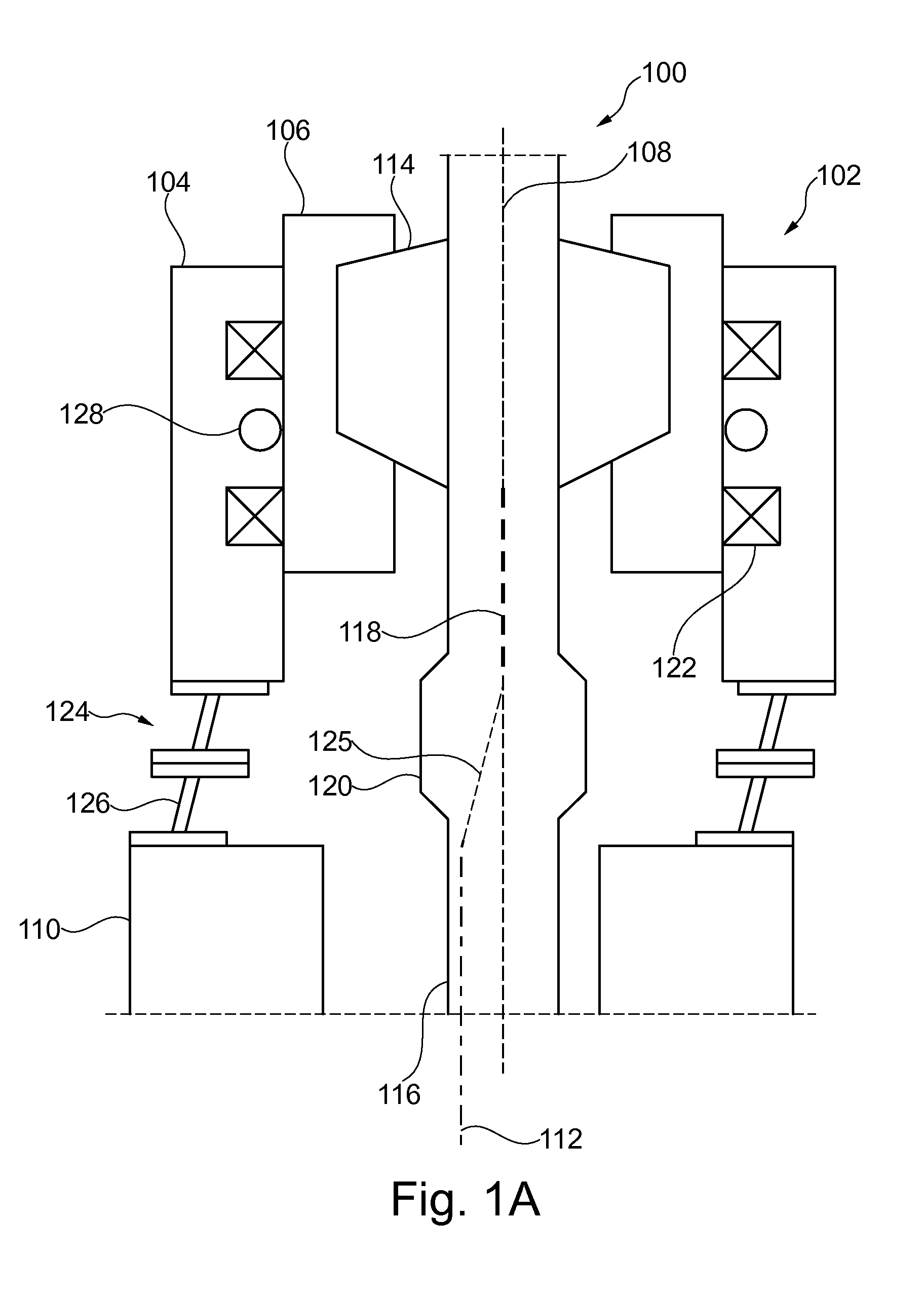
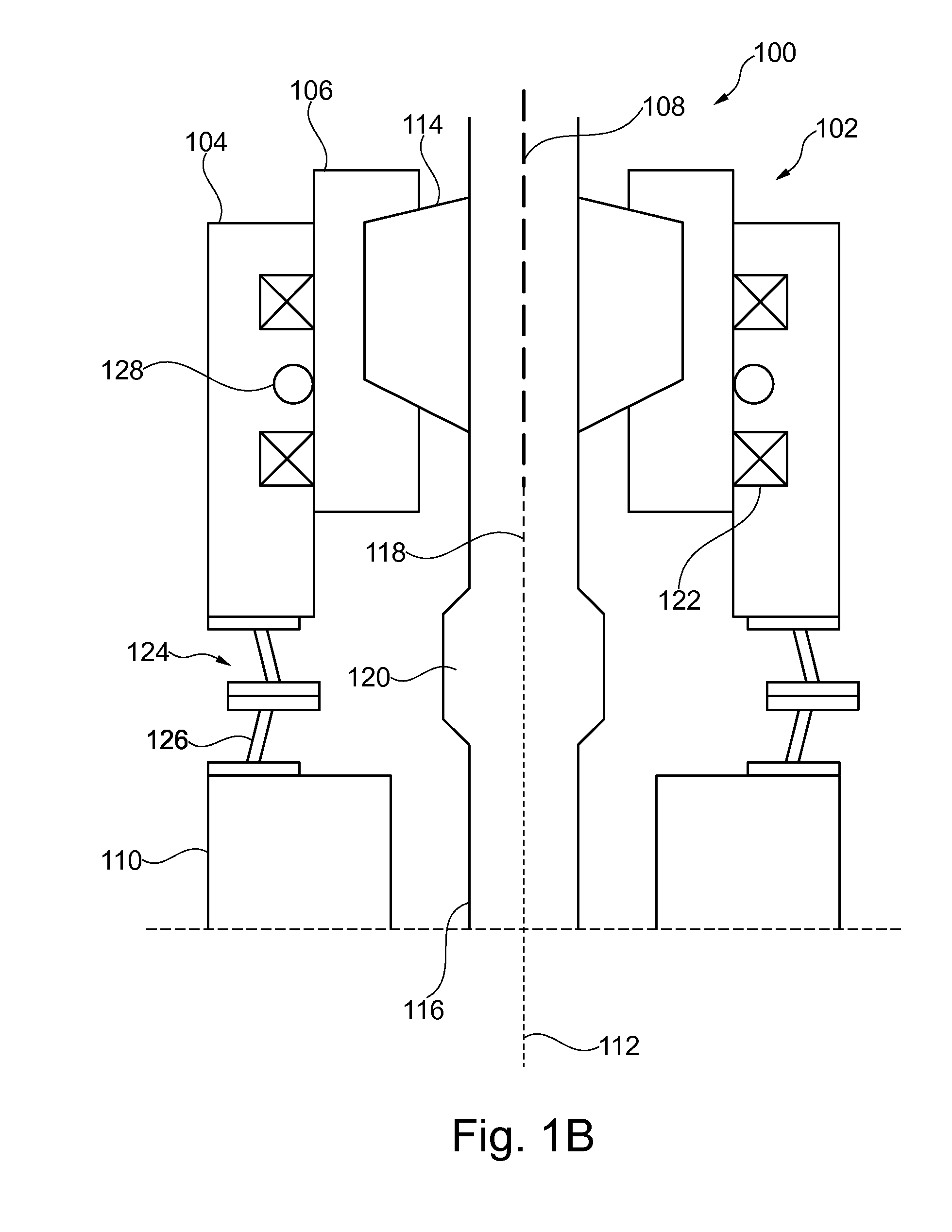
Due to aligning the RCD, BOP, and shaft with different components, misalignment between the RCD and shaft can result.
Misalignment between the pressure drilling system equipment and a wellhead can result in the drill shaft being eccentric in the RCD.
The eccentricity can produce side forces and lateral deformation in the rubber

Method used


Image

  • Management & control of a sealing element of a rotating control device
  • Management & control of a sealing element of a rotating control device
  • Management & control of a sealing element of a rotating control device

Examples


Example

[0026]The ensuing description provides preferred exemplary embodiment(s) only, and is not intended to limit the scope, applicability or configuration of the invention. Rather, the ensuing description of the preferred exemplary embodiment(s) will provide those skilled in the art with an enabling description for implementing a preferred exemplary embodiment of the invention. It being understood that various changes may be made in the function and arrangement of elements without departing from the spirit and scope of the invention as set forth in the appended claims.

[0027]Specific details are given in the following description to provide a thorough understanding of the embodiments. However, it will be understood by one of ordinary skill in the art that the embodiments maybe practiced without these specific details. For example, circuits may be shown in block diagrams in order not to obscure the embodiments in unnecessary detail. In other instances, well-known circuits, processes, algor...


PUM


Abstract

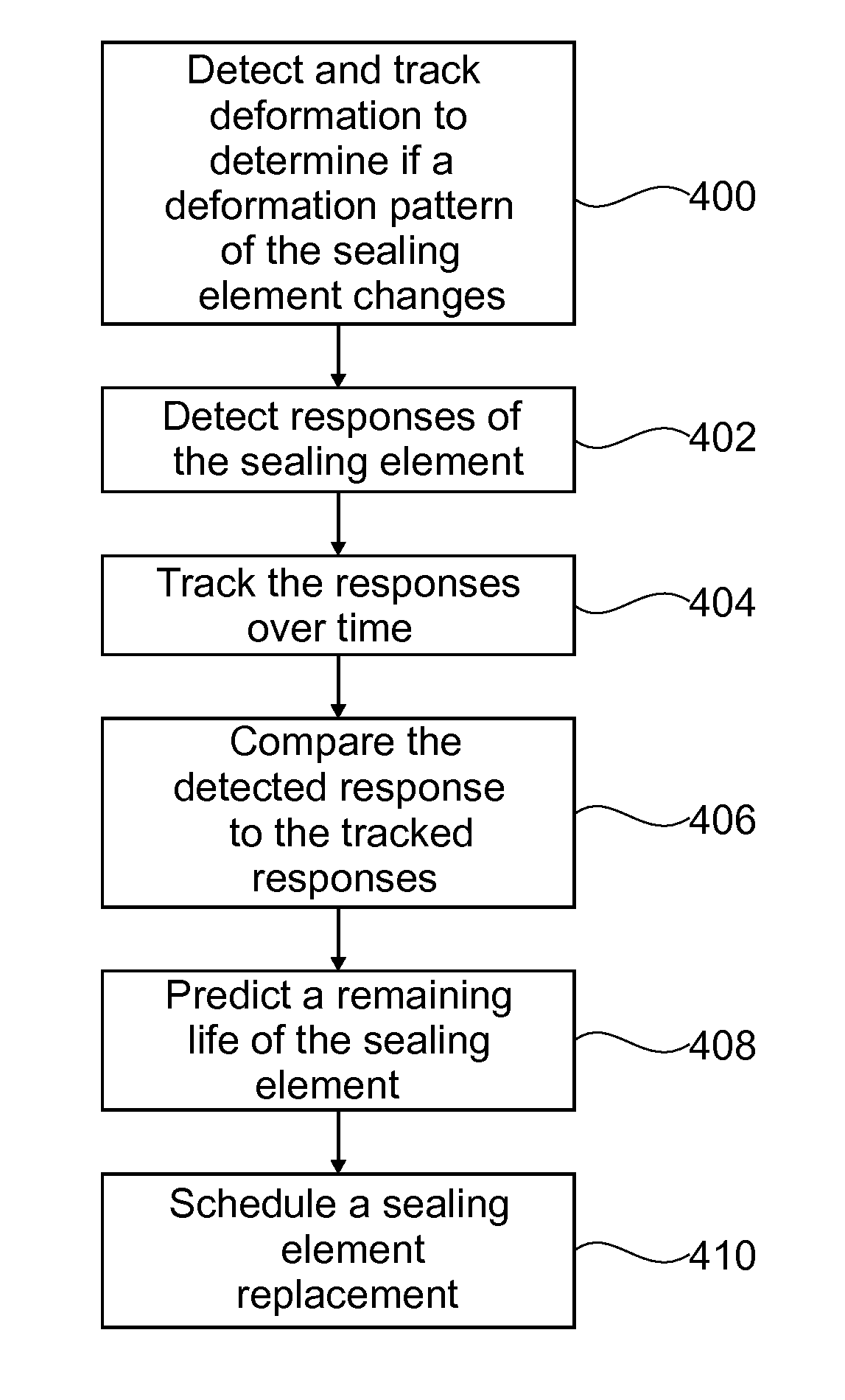
Managing operation of a sealing element is described. In some aspects, failure of the sealing element of a pressure drilling system may be predicted. Deformation of the sealing element as a tool joint is pulled through the sealing element may be detected and tracked to determine if a deformation pattern of sealing element changes. Responses of sealing element due to one or more of stress, strain, temperature, mechanical load, and pressure using a network of sensors around sealing element can be detected. Responses may be tracked over time. Detected responses are compared to tracked responses to identify changes in the symmetry of responses over time or changes in magnitude of responses over time. Changes are associated with fractures occurring within sealing element. A remaining life of sealing element is predicted based on the changes and replacement may be scheduled based at least in part on the predicted remaining life.

Description

CROSS REFERENCE TO RELATED APPLICATION(S)[0001]This application claims priority to Great Britain Patent Application No. 1405968.7, filed Apr. 2, 2014. The disclosure of priority application is hereby incorporated by reference herein in its entirety.BACKGROUND[0002]Managed pressurized drilling operations utilize oil rigs having a pressurized drilling annulus. A rotating control device (RCD) is mounted atop the annulus and includes a sealing element to seal the annulus, aiding in the creation of the pressurized drilling environment. Conventional management of and condition detection for sealing elements in managed pressure drilling operation equipment is based on pressure measurement above and below the sealing element. In some cases, two sealing elements may be used to seal the annulus. Conventional monitoring of such systems involves measuring the pressure between the two sealing elements. Such pressure monitoring techniques are capable of detecting performance degradation associate...

Claims


Application Information

Patent Timeline
IPC IPC(8): E21B44/00G01M13/00
CPCG01M13/005E21B44/00E21B47/007E21B33/00E21B33/068
Inventor JOHNSON, ASHLEY BERNARDFRANCIS, PAUL ANTHONY
Owner SCHLUMBERGER TECH CORP
Why Eureka
Try Eureka