Proximity sensor

a proximity sensor and sensor technology, applied in the field of radar systems, can solve the problems of not being able to discriminate robustly against target characteristics such as length, shape, orientation, and conventional proximity sensors also perform poorly in a stressing environmen

Inactive Publication Date: 2015-10-08
TECHNOLOGY SERVICE CORPORATION
View PDF39 Cites 70 Cited by
  • Summary
  • Abstract
  • Description
  • Claims
  • Application Information

AI Technical Summary

Benefits of technology

[0005]In accordance with an embodiment, a forward-looking proximity sensor comprises one or more antenna elements mounted on a carrier platform in a lateral direction of said carrier platform, said antenna elements being configured to transmit a modulated signal in a direction of travel of said carrier platform, said antenna elements receiving a reflected portion of said modul...

Problems solved by technology

These conventional proximity sensors, however, do not allow for robust discrimination of target characteristics such as length, shape, orientation, etc.
Conventional proximity sensors al...

Method used


Image

  • Proximity sensor
  • Proximity sensor
  • Proximity sensor

Examples


Embodiment Construction

[0030]Reference will now be made in detail to the present embodiments of the disclosure, examples of which are illustrated in the accompanying drawings. Wherever possible, the same reference numbers will be used throughout the drawings to refer to the same or like parts.

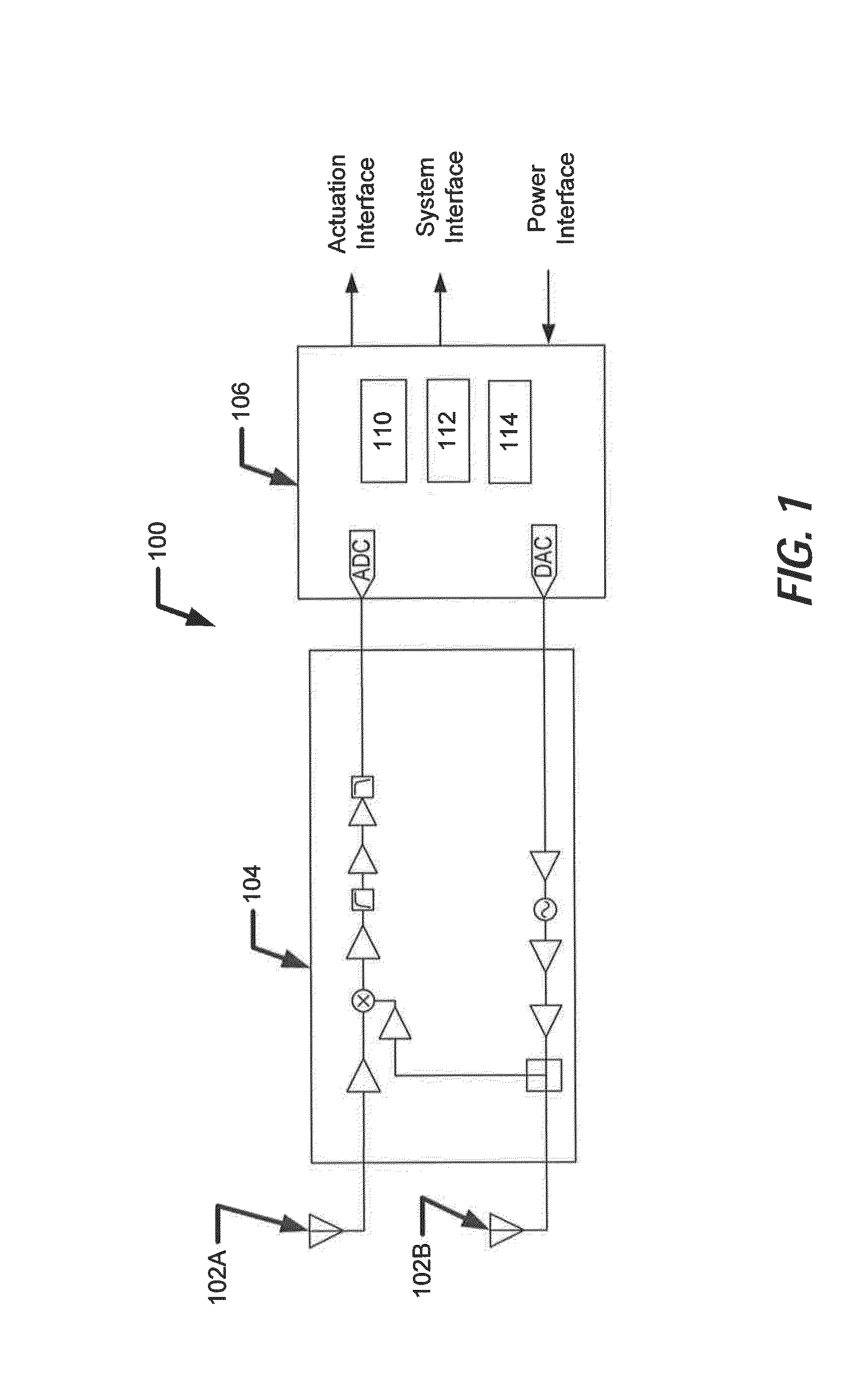
[0031]FIG. 1 illustrates a schematic diagram of an exemplary proximity sensor 100 according to an embodiment. Proximity sensor 100 includes one or more antennas 102A and 102B, an analog module 104, and a processing module 106. Antennas 102A and 102B may each be configured to transmit as well as receive signals, such as radio frequency (RF) signals, optical signals, laser signals, infrared signals, etc. Alternatively, one of antennas 102A or 102B may operate as a transmitting antenna configured to transmit the signals and another one of antennas 102A or 102B may operate as a receiving antenna configured to receive the signals. According to an embodiment, the signals transmitted by antennas 102A and 102B may be continu...


PUM


Abstract

A forward-looking proximity sensor comprises one or more antenna elements mounted on a carrier platform in a lateral direction of said carrier platform, said antenna elements being configured to transmit a modulated signal in a direction of travel of said carrier platform, said antenna elements receiving a reflected portion of said modulated signal from said target; and a processing unit configured to generate said modulated signal based on a baseband signal and a carrier signal, said processing unit further determining characteristics of said target based on said reflected portion of said modulated signal, said characteristics of said target indicating a range of said target and at least one feature of said target.

Description

RELATED APPLICATION(S)[0001]This application claims the benefit of priority to U.S. Provisional Application No. 61 / 709,397, filed Oct. 4, 2012, which is incorporated by reference herein in its entirety.FIELD OF THE INVENTION[0002]This disclosure relates to radar systems in general and proximity sensor based on radar sensing in particular.BACKGROUND OF THE INVENTION[0003]Radar sensors uses radio signals to detect targets. By analyzing the radio signals reflected from the targets, radar sensors may extract information about the targets, such as their shapes, sizes, velocities, etc. Radar sensors may serve as proximity sensors to determine a distance or proximity of a target based on the reflected signals. Conventional proximity sensors determine the proximity of a target based on a transmission delay of the radio signals reflected from the target or based on a Doppler frequency of the reflected signals.[0004]For example, missile systems may use proximity sensors to trigger a warhead w...

Claims


Application Information

Patent Timeline
IPC IPC(8): G01S13/66G01S13/88G01S13/34G01S13/89G01S13/02G01S7/41
CPCG01S13/66G01S13/0209G01S13/883G01S13/34G01S13/89G01S7/411G01S7/412G01S13/42
Inventor HOOPER, WILLIAM W.JOHNSON, MICHAEL A.
Owner TECHNOLOGY SERVICE CORPORATION
Why Eureka
Try Eureka