
Wireless tank level monitoring

a technology of level monitoring and wireless tanks, applied in the direction of liquid/fluent solid measurement, volume measurement, instruments, etc., can solve the problems of limited monitoring system, critical consequences for the storage area or local environment of the tank, and high risk of human monitoring

Active Publication Date: 2015-10-08
SILVERSMITH
View PDF7 Cites 19 Cited by
  • Summary
  • Abstract
  • Description
  • Claims
  • Application Information

AI Technical Summary

Benefits of technology

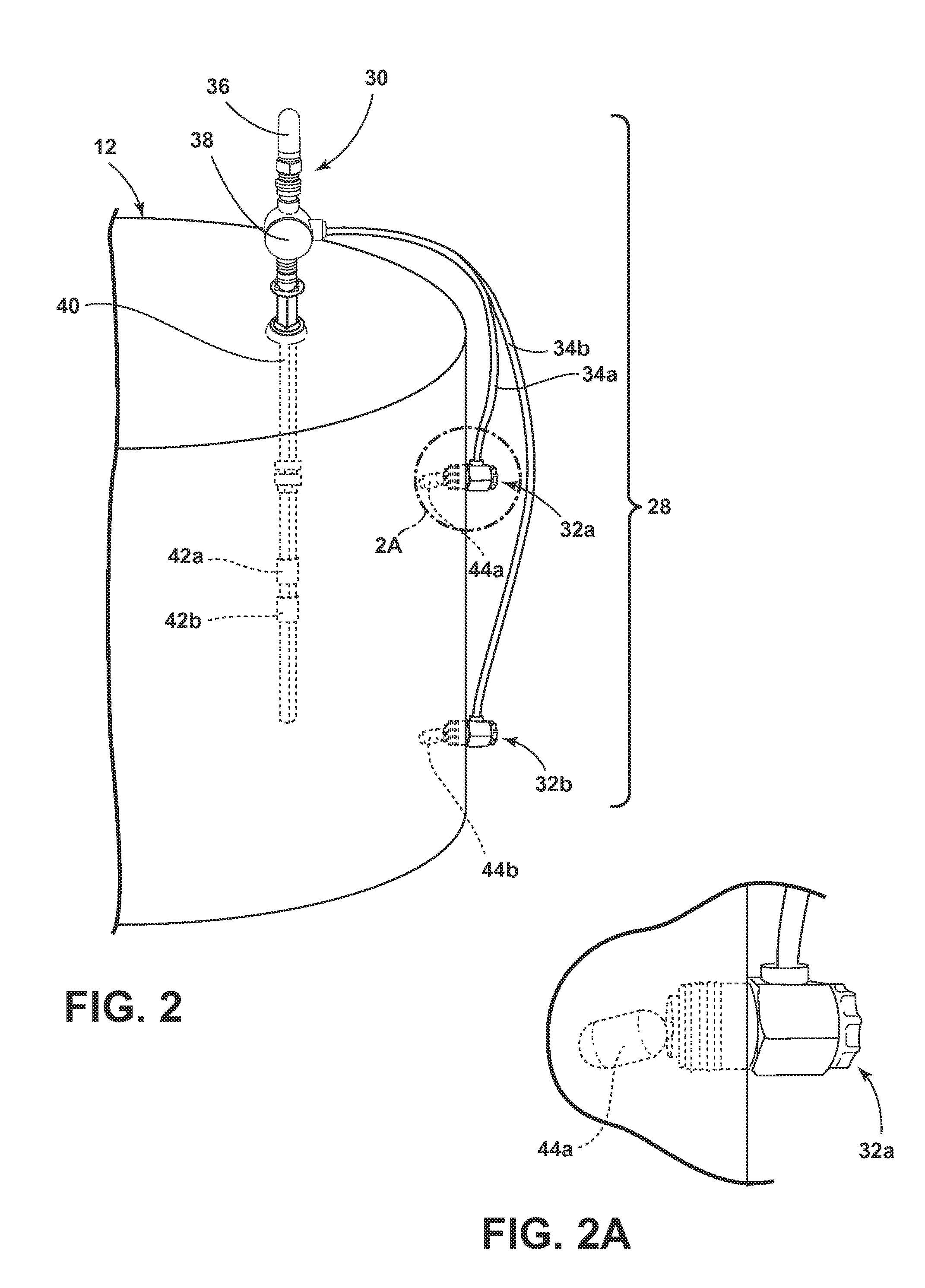
The invention is a wireless tank monitor system that can measure the level of liquid in a tank and communicate the information to a remote location. The system includes a level sensor, float sensors, a switch, controller, and transmitter. The controller can wake up at predetermined intervals and send data packets to the data collection center. The system can also detect conditions in the tank and increase the frequency of measuring and transmitting the data packets when the condition occurs. The data packets can be transmitted wirelessly, and the system may include a battery to power the processor. The system allows for remote monitoring of liquid levels in tanks, providing real-time information about tank inventory.

Problems solved by technology

Extremely hazardous material monitoring may require an electric monitor without any electric sparking or a securely enclosed electric system which may otherwise trigger a reaction.
In an event where a tank may have a spill or overflow, there may critical consequences to the tank storage area or local environment.
Monitors are known with an alert function, but may not alert a data collection center as the spill or overflow may be imminent, before a critical situation may occur.
Classically, human monitoring has been used to monitor tanks with hazardous materials, but human monitoring may be very dangerous.
Conversely, a monitoring system may be limited by the programming to readings by specific times or intervals, where a human monitoring system may be more accurate or incident driven.
The reality is that the malfunctions, spills, or overflows are infrequent and a high frequency sampling requires a lot of battery power.
Furthermore, hazardous locales may require a low power monitoring system, such as battery power, where electricity may be too dangerous to run or use.

Method used


Image

  • Wireless tank level monitoring
  • Wireless tank level monitoring
  • Wireless tank level monitoring

Examples


Embodiment Construction

[0026]In the background and the following description, for the purposes of explanation, numerous specific details are set forth in order to provide a thorough understanding of the technology described herein. It will be evident to one skilled in the art, however, that the exemplary embodiments may be practiced without these specific details. In other instances, diagrams show structures and devices facilitating description of the exemplary embodiments of the invention.

[0027]References to the drawings describe the exemplary embodiments. These drawings illustrate certain details of specific embodiments that implement an apparatus, method, or product described herein. However, the drawings should not impose any limitations that may be present in the drawings. The module, method, or product may be any sensing apparatus or transmission product and implementation thereof for accomplishing intended monitoring operations.

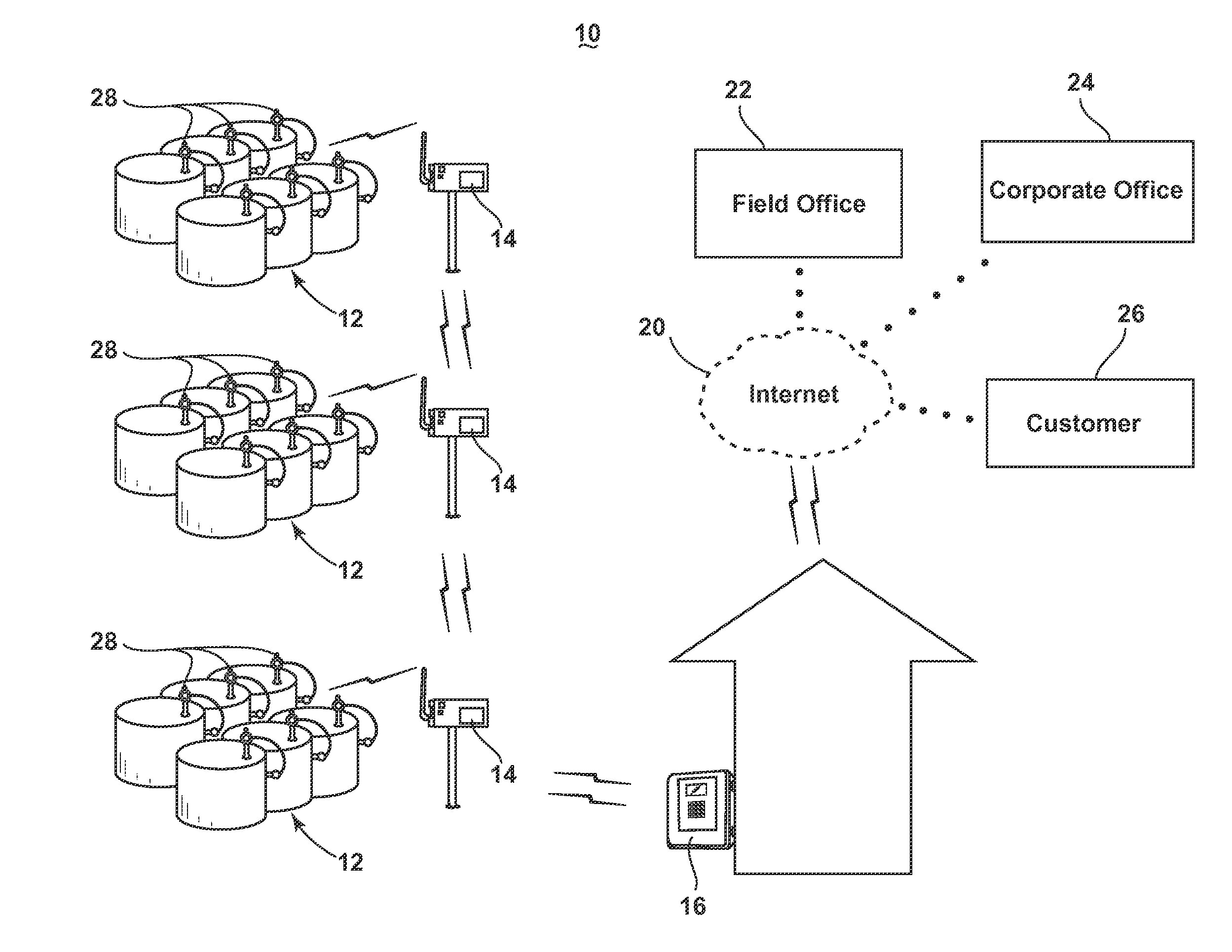
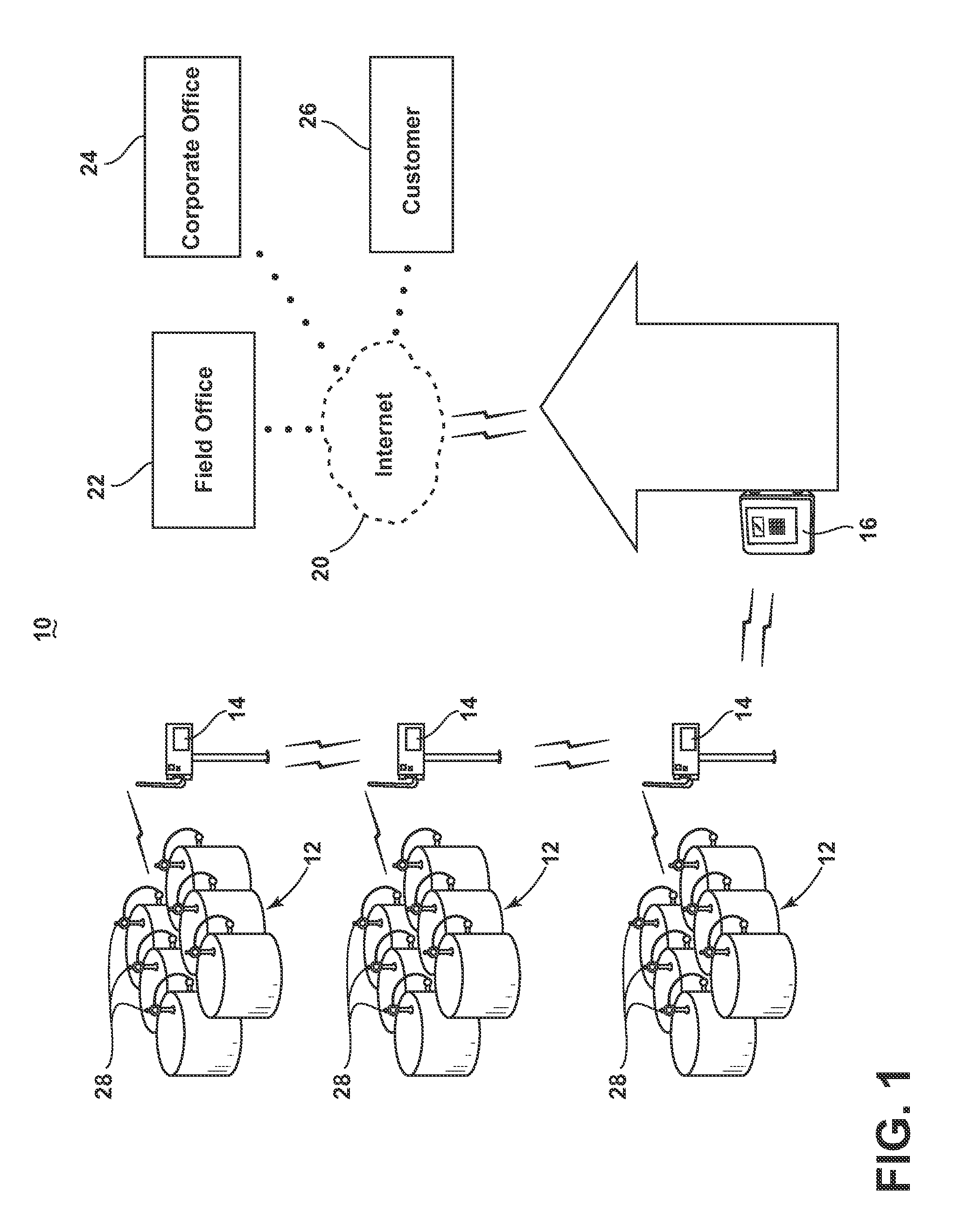
[0028]Referring now to the drawings and FIG. 1 in particular, clusters ...


PUM


Abstract

A tank level monitoring system with wireless transmission capability. The monitoring system includes a wireless tank monitor for level sensing and connected to one or more float level switches. The system regularly measures the level of fluid in a tank, but may change the measurement rate based upon the float switch. This system actively monitors conditions of a tank and alerts a user when conditions exceed a predetermined parameter.

Description

[0001]This application claims the benefit of U.S. Provisional Patent Application No. 61 / 976,044, filed Apr. 7, 2014, which is incorporated herein by reference in its entirety.FIELD OF THE INVENTION[0002]This invention relates to storage tank monitoring. In one of its aspects, the invention relates to monitoring the level of liquid in oil well storage tanks. Oils or liquids that may be stored include but are not limited to black oils, volatile oils, gas condensates, water, or any other type of liquid. In another of its aspects, the invention relates to wireless monitoring of liquid storage tanks from a remote location.BACKGROUND[0003]Battery operated, wireless monitoring of well tanks from a remote monitoring location have been used in Class 1 Division 1 locales. Tanks in the remote locations may store any type of contents such as hazardous materials such as oil or gasoline, or may store a multitude of chemicals or any other content which may be desirable to store at a remote locatio...

Claims


Application Information

Patent Timeline
IPC IPC(8): G08B21/18G08B5/22
CPCG08B5/22G08B21/182G01F23/683G01F23/703G01F22/00G01F23/0015G01F23/802
Inventor SILVERS, DAVID
Owner SILVERSMITH
Learn More