Choke and choke core

a choke core and choke core technology, applied in the direction of transformer/inductance details, inductances with magnetic cores, inductances, etc., can solve the problems of large losses in the grid, grid dimensioning is too large, ripple current components do not precisely compensate each other, etc., to achieve efficient energy transport, low weight, and high efficiency

Active Publication Date: 2015-10-08
SUMIDA COMPONENTS & MODULES
View PDF9 Cites 16 Cited by
  • Summary
  • Abstract
  • Description
  • Claims
  • Application Information

AI Technical Summary

Benefits of technology

[0014]In view of new power safe technologies, such as in automotive engineering in the domain of hybrid and electro vehicles there is a growing demand for chokes for interleaved PFC circuits with low weight and high efficiency so as to safe energy on the one hand (weight) and at the other hand to efficiently transport energy, for instance, if motion energy in electric or hybrid vehicles is retrieved with a generator and supplied into the on-board electrical grid. It is therefore a task of the present invention to provide a choke with an optimized core geometry for a choke coil pair for use in interleaved PFC-application, which is compact and has small losses and a low weight.

Problems solved by technology

Hereby greater losses occur in the grid and the grid has to be dimensioned larger than actually necessary.
At different duty cycles the ripple current components do not precisely compensate each other.

Method used


Image

  • Choke and choke core
  • Choke and choke core
  • Choke and choke core

Examples


first embodiment

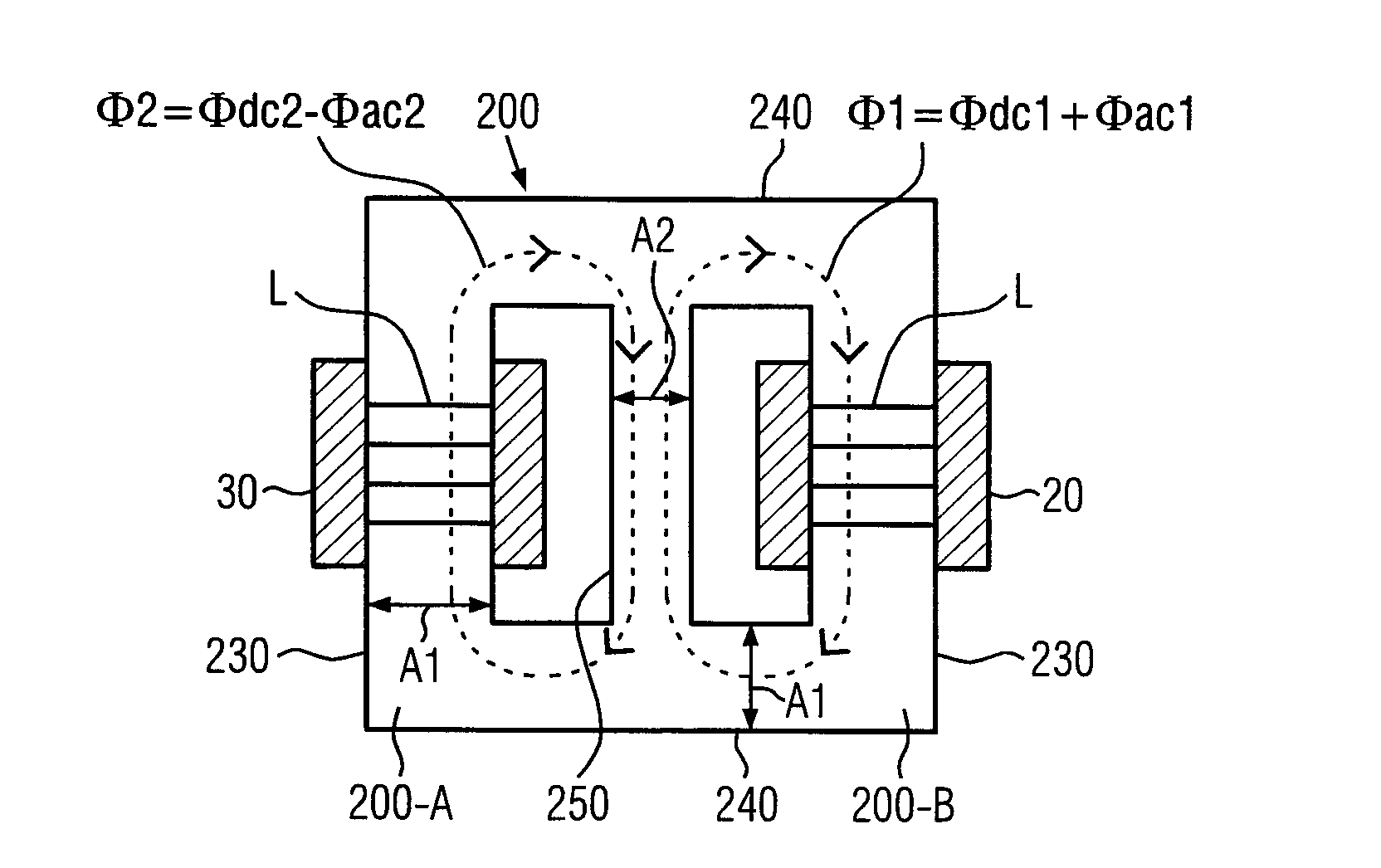
[0043]FIG. 5 shows an implementation of the present invention with two E-shaped formed components 210 and 220, which are connected such that their free ends meet. To illustrate the E-shape in FIG. 5 larger gaps L1, L2 and L3 between the free ends of the two E-shaped parts 210 and 220 are shown. When implementing, as far as possible, no gaps L1, L2 and L3 should occur in order to avoid undefined air gaps, i.e. the ending surfaces on the free ends of the E-shaped parts have to be manufactured so precisely, that they lie in one plane, so that no air gaps occur. Air gaps are exemplarily selectively introduced in the lateral legs 230 in the area of the coils 20 and 30. The cross section A2 of the middle leg 250 is, as explained in detail above, smaller than the cross section A1 of the lateral legs 240 and 230.

[0044]In order to avoid a situation, as it can occur with E-shaped parts with the three gaps L1, L2 and L3, two U-shaped core parts 260 and 270 can be used, which are connected suc...

third embodiment

[0045]FIG. 6A shows a schematic top view of a core from two U-shaped parts 260 and 270 with a middle leg 250 according to a second and third embodiment of the present invention. In FIG. 6A the meeting edges of the free ends of the U-parts 260 or 270 are not visible. The coils 20 and 30 are positioned on the coils carrying lateral legs 230 of the core. The middle leg 250 fills the gap between the coils 20 and 30 and also forms a magnetic short-circuit between the lateral legs 240, so that two magnetic loops are formed. The air gap L in the lateral legs 230 in the area of the coils 20 and 30 leads to an operation outside of the magnetic saturation in the lateral legs and, at the same time, to a lower coupling of less than one percent between the two loops, respectively loops 20 and 30.

[0046]FIG. 6B shows a perspective view of the scheme of FIG. 6A according to a second embodiment with an extracted middle leg 350. FIG. 6B shows only the core arrangement without the coil windings 20 and...


PUM

PropertyMeasurementUnit
power factoraaaaaaaaaa
frequenciesaaaaaaaaaa
magnetic resistance RMAaaaaaaaaaa

Abstract

The present invention relates to a choke with two coils and a core for interleaved applications in step-up or step-down circuits or power factor compensation circuits. The core comprises several core sections with several lateral legs and a middle leg, whereby the core is designed such, that a coupling factor k of the two coils is smaller than 3%-5%. Furthermore, the core is designed such, that the core section form two loops with the middle leg as a common section, whereby each of the two coils lies on different loops outside of the common section. The lateral legs have a cross section A1 and the middle leg for the common section has a cross section A2<2×A1.

Description

FIELD OF THE INVENTION[0001]The present invention relates to a choke with two coils and one core, optimized to be used in step-up or step-down circuits or power factor compensation (PFC) filters in an interleaved configuration. Furthermore, the present invention relates to an optimized double coil core for interleaved applications in step-up and step-down or power factor compensation (PFC) circuits.BACKGROUND OF THE INVENTION[0002]In the following, the term “choke” relates to a configuration from one or several coils placed on a common core.[0003]A step-up or step-down circuit refers to a circuit, which can increase or decrease a direct-current voltage. Step-up and Step-down circuits operate according to similar principles like power factor compensation filters and partially use the same components.[0004]A power factor correction is imposed in Germany for electric loads over 75 watt since 1 Jan. 2001 by the electromagnetic compatibility norm (EMC). Power factor describes the rate be...

Claims


Application Information

Patent Timeline
Patent Type & Authority Applications(United States)
IPC IPC(8): H01F27/24H01F27/28
CPCH01F27/28H01F27/24H01F37/00
Inventor WINKLER, JOHANNHOLZINGER, ERNSTLUDWIG, ROBERTKEBAISY, IYADJUNGWIRTH, HERBERT
Owner SUMIDA COMPONENTS & MODULES
Why Eureka
Try Eureka