Wiring member

a technology of wiring member and wire, which is applied in the direction of coupling device connection, inductance reduction, aperture leaage reduction, etc., can solve problems such as failure to fix

Active Publication Date: 2015-10-08
HITACHI METALS LTD
View PDF5 Cites 20 Cited by
  • Summary
  • Abstract
  • Description
  • Claims
  • Application Information

AI Technical Summary

Benefits of technology

[0010]A wiring member according to an aspect of the invention is simply structured and capable of restricting movement of an electromagnetic wave absorber in an axial direction.

Problems solved by technology

In the structure of the shield cable described in Japanese Unexamined Patent Application Publication No. 6-176823, the magnetic body, if not covered with a covering member, would move in the axial direction as a result of sliding over the outer surface of the shield layer, possibly failing to fix the magnetic body at an appropriate position.

Method used


Image

  • Wiring member
  • Wiring member
  • Wiring member

Examples


embodiment

[0018]Referring now to the drawings, and more particularly to FIGS. 1-6, there are shown exemplary embodiments of the methods and structures according to the present invention.

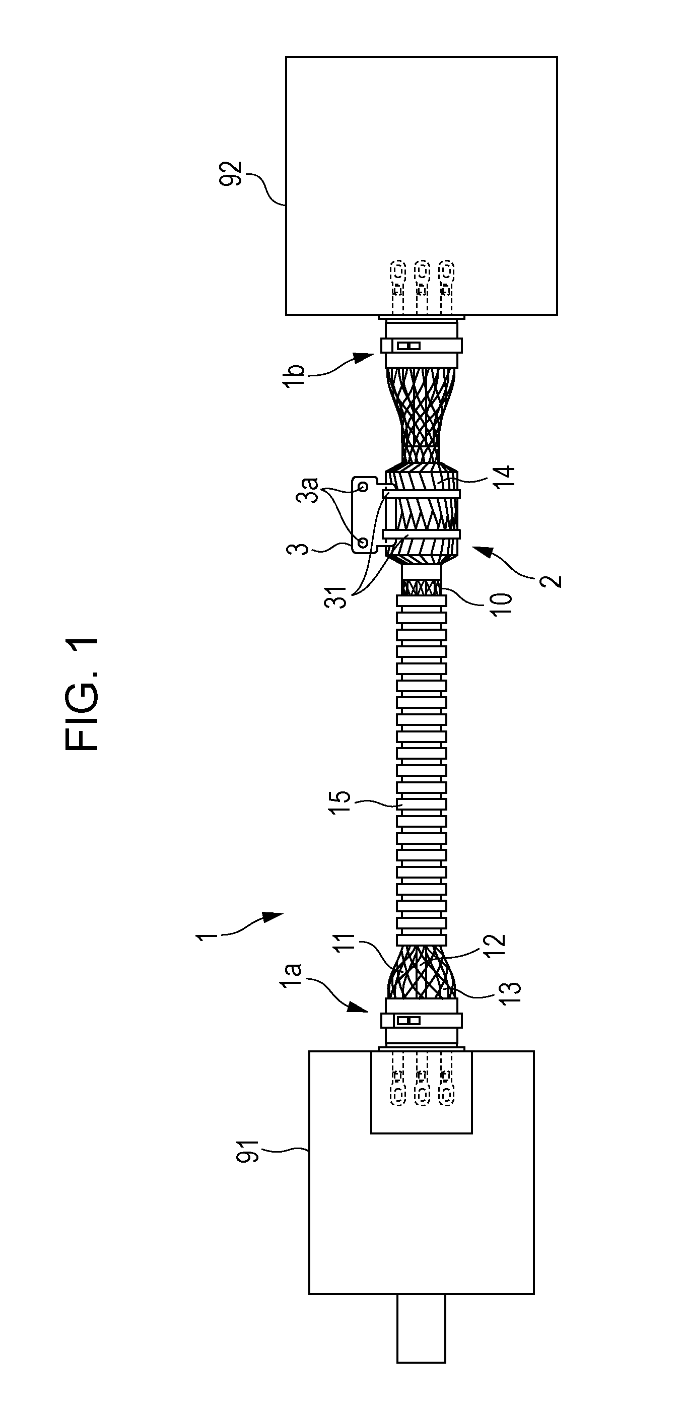
[0019]FIG. 1 is a schematic diagram of a wire harness 1 according to an embodiment of the present invention and an electric motor 91 and an inverter 92 connected together by the wire harness 1. The wire harness 1 is an example of a wiring member according to an aspect of the invention.

[0020]The wire harness 1 is installed in, for example, a vehicle. The wire harness 1 is used to feed driving electric current, output from the inverter 92 after being subjected to pulse width modulation (PWM) control, to the electric motor 91, which is a driving source for generating force to drive the vehicle. The driving electric current contains harmonics caused by switching of a switching element such as a power transistor.

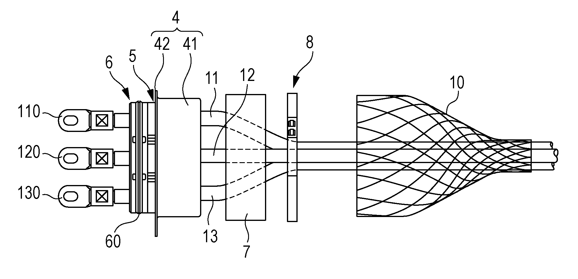
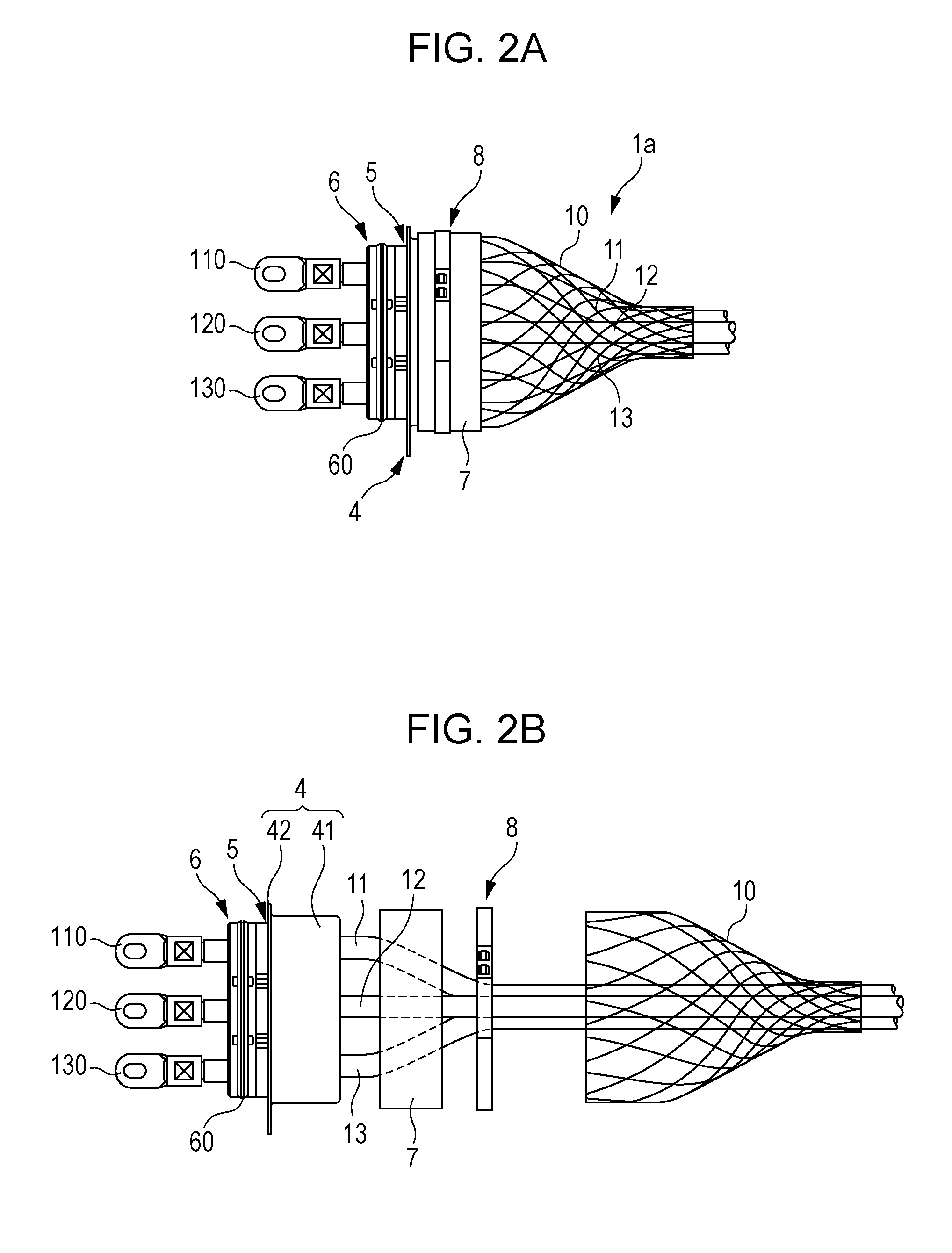
[0021]The wire harness 1 includes a first electric wire holding portion 1a, fixed to a casing of the ele...


PUM


Abstract

A wire harness includes first to third electric wires, a braid shield that covers the first to third electric wires, and a tube-shaped electromagnetic wave absorber having a through hole that allows the first to third electric wires to be inserted therethrough, the electromagnetic wave absorber absorbing electromagnetic waves emitted from the first to third electric wires. The braid shield covers an outer circumferential surface and two axial end surfaces of the electromagnetic wave absorber to restrict movement of the electromagnetic wave absorber in an axial direction. The braid shield satisfies 1≦n≦15 and 10≦m≦50 where the number of carriers of the braid shield is denoted by n and the number of ends of the braid shield is denoted by m.

Description

[0001]The present application is based on Japanese patent application No. 2014-076248 filed on Apr. 2, 2014, the entire contents of which are incorporated herein by reference.BACKGROUND OF THE INVENTION[0002]1. Field of the Invention[0003]The present invention relates to wiring members, particularly to a wiring member including an electromagnetic wave absorber that reduces noise emitted from an electric wire.[0004]2. Description of the Related Art[0005]Some wiring members for connecting devices to each other include a shield and an electromagnetic wave absorber to reduce noise emitted from electric wires (see, for example, Japanese Unexamined Patent Application Publication No. 6-176823).[0006]A shield cable described in Japanese Unexamined Patent Application Publication No. 6-176823 includes multiple electric wires, a shield layer that covers these multiple electric wires, and a tube-shaped magnetic body. The magnetic body is made of a material such as ferrite. The magnetic body is ...

Claims


Application Information

Patent Timeline
Patent Type & Authority Applications(United States)
IPC IPC(8): H05K9/00
CPCH05K9/0009H01F17/06H01F27/263H01F2017/065H01R13/5202H01R13/65912H01R13/6592H01R2201/26H05K9/0018H05K9/0098
Inventor IMAHORI, MASAAKIHAYAKAWA, YOSHIKAZUFUTATSUMORI, TAKAHIRO
Owner HITACHI METALS LTD
Why Eureka
Try Eureka