Lenticular capsule-expanding device

a technology of expanding device and lenticular capsule, which is applied in the field of lenticular capsule expansion device, can solve the problems of insufficient eyesight, loss of force, and difficulty in thickness change of crystalline lens l, and achieve the effect of effective adjustment function of intraocular lens, high degree of accuracy, and effective exertion of intraocular lens adjustment function

Inactive Publication Date: 2015-10-15
XLENS TECH INC
View PDF4 Cites 42 Cited by
  • Summary
  • Abstract
  • Description
  • Claims
  • Application Information

AI Technical Summary

Benefits of technology

[0040]In some embodiments, it is preferable that an intraocular lens is arranged between the front supporting section and the rear supporting section. With this, the lens capsule device and the intraocular lens work together, and therefore the adjustment function of the intraocular lens can be exerted with high degree of accuracy
[0041]In some embodiments, it is preferable that the intraocular lens includes an optical section made of a lens and a plurality of arm sections provided at a peripheral portion of the optical section, one end portion of each arm section is movably connected to a peripheral portion of the optical section, and the other end portion of each arm section is engaged with the connecting section, when the other end portion of the arm section is moved in the approaching / separating direction depending on a degree of expansion of the connecting section radially outward, the optical section to which the one end portion of the arm section is attached moves between the front supporting section and the rear supporting section in a front-back direction. With this, when the front supporting section and the rear supporting section move in the approaching direction between the front supporting section and the rear supporting section and the degree of radially outward expansion of the connecting section increases, the other end portions of the arm sections of the intraocular lens move in the separating direction, and in accordance with the movement, the optical section of the intraocular lens can move rearward. Further, when the front supporting section and the rear supporting section move in the separating direction and the degree of radially outward expansion of the connecting section decreases, the other end portions of the arm sections of the intraocular lens move in the approaching direction, and in accordance with the movement, the optical section of the intraocular lens can move forward. As explained above, by working the lenticular capsule-expanding device and the intraocular lens together, the adjustment function of the intraocular lens can be exerted effectively.
[0042]In some embodiments, it is preferable that the one end portion of the arm section connected to a peripheral portion of the optical section and the other end portion of the arm section to be engaged with the connecting section are arranged on opposite sides with respect to a center of the optical section. With this, the length / distance of the arm section from one end portion to the other end portion becomes longer and the movement of the other end portions of the arm sections in the approaching direction can be effectively converted into the movement of the optical section in the front-back direction. Therefore, even by slight movements of a lens capsule in accordance with slight contraction and relaxation of a ciliary muscle of a ciliary body, the adjustment function of the intraocular lens can be effectively exerted.

Problems solved by technology

On the other hand, it is also known that the contents of the crystalline lens L and the lens capsule S become hardened to lose the flexibility, resulting in difficulty of thickness changes of the crystalline lens L, which loses the force of voluntarily adjusting the focal point (hereinafter referred to as “focusing ability”) when seeing a near distance from the state of seeing a far distance (which will be called presbyopia).
However, a single focus lens is generally made of a material such as a PMMA (Poly Methyl Methacrylate), silicon, acrylic, etc., which is not capable of changing a thickness of the single focus lens itself For this reason, it was inevitable to avoid the loss of focusing ability after the surgery.
However, in such multifocal intraocular lens, there are reports that patients complain of a halo phenomenon in which an object looks with light rings, a glare in which an object looks glistening, insufficient eyesight, or insufficient contrast sensitivity.
Thus, such multifocal intraocular lenses could not have sufficiently satisfied patient's requests.
Therefore, it is difficult to accurately convert slight contraction and relaxation of a ciliary muscle of a ciliary body into movements of an optical section in a front-back direction.
This in turn cannot accurately exert the adjustment function of the intraocular lens.
For this reason, slight contraction and relaxation of a ciliary muscle of a ciliary body cannot be transmitted accurately, which prevents accurate exertion of the adjustment function of the intraocular lens.
This causes adhesion of an anterior capsule and a posterior capsule of a crystalline lens, resulting in atresia of the lens capsule equator.
That is, a central portion of the lens capsule becomes turbid or cloudy, causing difficulty in passing light, which in turn results in poor visual acuity.
The equator of the crystalline lens adheres in the front-back direction, causing fibroplasia, which results in hardening of the equator.

Method used


Image

  • Lenticular capsule-expanding device
  • Lenticular capsule-expanding device
  • Lenticular capsule-expanding device

Examples


first embodiment

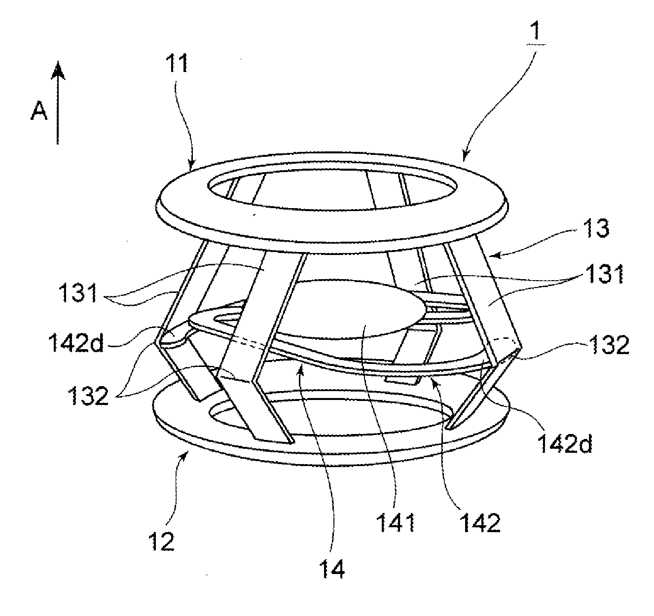
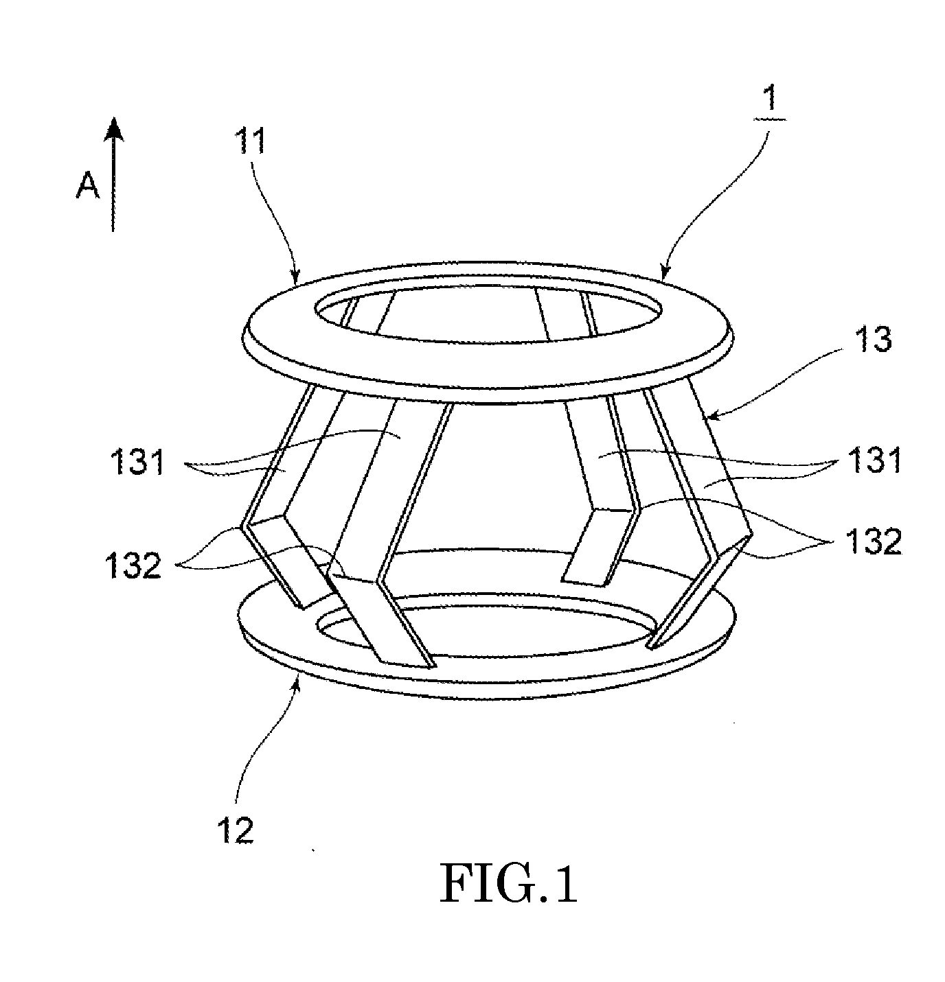
[0066]Next, a lenticular capsule-expanding device (hereinafter may be simply referred to as “the present device”) and an intraocular lens (hereinafter may be simply referred to as “the present lens”) to be arranged inside the present device according to the present disclosure will be explained with reference to FIGS. 1 to 7. The following explanation will be made, assuming that the arrow direction A shown in figures denotes a direction toward a “front” side and the opposite direction denotes a direction toward a “rear / back” side.

Structure of Device

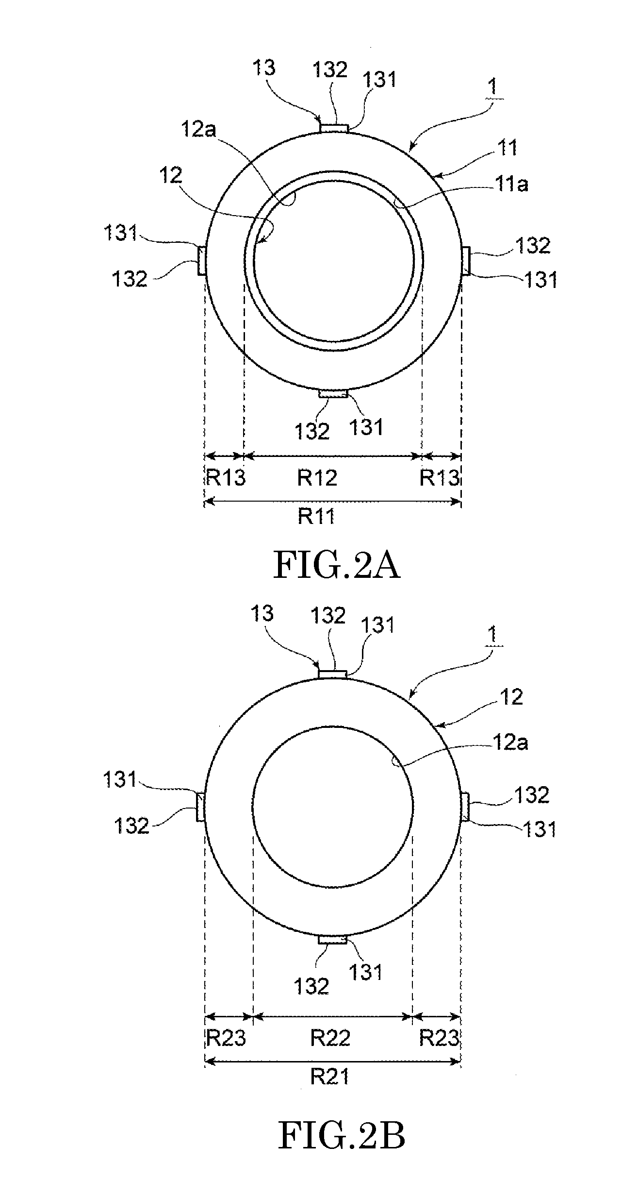
[0067]As shown in FIGS. 1 to 7, the present device 1 is configured to be arranged in a lens capsule S in which the anterior capsule Sf was cut in a surgery such as a cataract surgery, etc. The present device 1 is, as shown in FIG. 1, equipped with a front supporting section 11 to be positioned at a front side in the lens capsule S, a rear supporting section 12 to be positioned at a rear side in the lens capsule S, and a connecting section ...

second embodiment

[0123]Next, a second embodiment of a lenticular capsule-expanding device according to the present disclosure will be explained with reference to FIGS. 8A and 8B. Hereinafter, the following explanation will be directed to the structure different from that of the aforementioned embodiment, and the explanation of the same structure will be omitted by allotting the same reference numeral or symbol.

[0124]In the present device 2 according to this embodiment, the connecting section 13 is difference in thickness and width at the front side and the rear side with respect to the bending portion 132.

[0125]For example, in the connecting section 13, as shown in FIG. 8A, the thickness Df of the front side portion of the connecting member 231 arranged on the front side of the bending portion 132 is made thinner than the thickness Db of the rear side portion of the connecting member 231 arranged on the rear side of the bending portion 132.

[0126]Further, in the present device 2′ according to a modif...

third embodiment

[0128]Next, a third embodiment of a lenticular capsule-expanding device according to the present disclosure will be explained with reference to FIGS. 9A to 9C. Hereinafter, the following explanation will be directed to the structure different from that of the aforementioned embodiments, and the explanation of the same structure will be omitted by allotting the same reference numeral or symbol.

[0129]In the present device 3 according to this embodiment, as shown in FIG. 9A, the connecting section 13 is provided with an engaging portion 15a for engaging the arm section 142 of the present lens 14 on the inner side of the bending portion 132. Concretely, this engaging portion 15a is protruded radially inward from the slightly rearward portion of the inner side of the bending portion 132, and is an elastic member having a tip end curved forward in an arc-shaped manner. With this structure, by forcibly inserting the tip end portion 142c of the arm section 142 into between the tip end porti...


PUM


Abstract

A lenticular capsule-expanding device is arranged in a lens capsule in a cataract surgery, etc. The device includes a front supporting section to be arranged in contact with an inner surface of an anterior capsule, the front supporting section, a rear supporting section to be arranged in contact with an inner surface of a posterior capsule, the rear supporting section being arranged behind the front supporting section, and a connecting section that connects the front and rear supporting sections in a manner as to have an urging force for separating the front and rear supporting sections in a separating direction. By the urging force of the connecting section, the front supporting section presses against the inner surface of the anterior capsule and the rear supporting section presses against the inner surface of the posterior capsule.

Description

CROSS-REFERENCE TO RELATED APPLICATION[0001]This is a continuation of International Application PCT / JP2013 / 081177, with an international filing date of Nov. 19, 2013, claiming a priority to Japanese Patent Application No. 2012-282287, filed on Dec. 26, 2012, the contents of which are incorporated herein by reference in their entirety.BACKGROUND OF THE INVENTIONS[0002]1. Field of the Invention[0003]The present disclosure relates to a lenticular capsule-expanding device to be arranged in a lens capsule, and also relates to an accommodative intraocular lens device including the lenticular capsule-expanding device and an intraocular lens arranged in the lenticular capsule-expanding device.[0004]2. Description of the Related Art[0005]The following description of related art sets forth the inventor's knowledge of related art and certain problems therein and should not be construed as an admission of knowledge in the prior art.[0006]Normally, focusing of a human eye (hereinafter simply ref...

Claims


Application Information

Patent Timeline
Patent Type & Authority Applications(United States)
IPC IPC(8): A61F2/16
CPCA61F2/1629A61F2002/1682A61F2/1694A61F2/16015
Inventor AKURA, JUNSUKE
Owner XLENS TECH INC
Why Eureka
Try Eureka